
Aluminum materials used in Zhongwei manifold projects
Our custom aluminum hydraulic manifolds (also written as aluminium hydraulic manifolds) commonly use 6061-T6, 6082-T6 and 7075-T6. Our machining experience also covers customer-specified 2017, 2024 and 6110. The exact alloy, temper and supply form are confirmed for each order.
6061-T6
A familiar option for many aluminum manifold projects. We connect the specified material to the cavity geometry, thread engagement, sealing features and finish requirements, so material procurement and machining follow one approved definition.
6082-T6
A specification encountered on European projects. We retain 6082 when the design calls for it; replacing it with 6061 requires a review of the actual material and component requirements.
7075-T6
Our commonly used high-strength aluminum option. It can support designs with demanding local loads around cartridge threads. We review the machining, assembly and finish requirements without assigning a universal pressure rating.
For 2017, 2024 and 6110 projects, retain the complete material designation and requested condition. On 2017, 2024 and 7075, anodized appearance deserves early discussion. Our supplier coordination and sample approval address that issue alongside the drawing requirements.
Compare Chinese, European and US aluminum designations
Use this table to identify the material reference on an international drawing and the questions to resolve before purchasing. Matching alloy numbers help align the chemistry reference. A different suffix, temper or product specification can still change the requirements.
| China Grade / purchasing reference | Europe EN AW reference | US AA reference | Relationship and checks |
|---|---|---|---|
| 6061 | EN AW-6061 | AA 6061 | Same alloy-number reference Check chemistry against the specified standard, then match temper, product form and section. 6061 and 6082 are separate alloys. |
| 6082 | EN AW-6082 | AA 6082 | Same alloy-number reference Confirm the required product specification and availability. An AA designation does not by itself confirm ASTM product compliance or local stock. |
| 7075 | EN AW-7075 | AA 7075 | Same alloy-number reference Retain the exact temper. T6, T651 and T73-family conditions must not be treated as one requirement; strength, corrosion exposure and stress relief need review. |
| 2017 | EN AW-2017A | AA 2017 | European variant for comparison 2017A is a distinct registered alloy from 2017. The European entry is a comparison candidate, not an approved replacement. Confirm chemistry and temper. |
| 2024 | EN AW-2024 | AA 2024 | Same alloy-number reference Match the exact temper and product form. Review corrosion protection and anodized appearance alongside the required mechanical properties. |
| 6110 (project reference) | EN AW-6110A | AA 6110 | European variant for comparison 6110A and 6110 are distinct registered alloys. Confirm the governing specification on the Chinese supply certificate; no GB equivalence or substitution is asserted here. |
The Chinese references use the project’s applicable GB material specification or purchasing specification. GB/T 3190 covers wrought-aluminum chemistry. EN AW references are used in Europe with the applicable EN specifications. AA numbers belong to the international alloy registration system administered by the Aluminum Association; they are not a complete US product specification.
For 2017/2017A and 6110/6110A, the table intentionally shows comparison candidates. These pairs have distinct registered compositions. Do not remove the “A” suffix or approve a substitution from a name match. For 6110 supplied in China, establish the certificate’s governing standard or supplier specification before purchase.
Designation references: GB/T 3190-2020; BS EN 573-3; Aluminum Association registered alloy compositions; Hydro EN AW-6110A reference; EURAL 2017A reference. Use the standard edition and product requirements specified for the order.
Make the temper and stock form part of the order
“6061” or “7075” identifies an alloy, but leaves important manufacturing and acceptance requirements open. We review the complete designation, material record and stock form before setting the machining route.
Temper and mechanical properties
Keep T6, T651 or another specified condition on the drawing and order. Stress-relieved conditions and other heat-treatment conditions are not silent substitutes for one another. Compare the required tensile and yield properties, elongation and any additional requirements using the applicable product and section limits.
Plate, bar or another specified form
A cut plate blank and an extruded bar need not share the same delivery requirements. Identify the stock form, dimensions and material specification. For a block with substantial material removal, we plan machining allowance, setup and finishing around the approved stock and geometry.
Material record and batch identity
Match the purchased material to its identification and agreed certificate. Keep the alloy, temper, applicable specification and batch connection available for delivery documentation. Any proposed change is resolved before manufacturing.
For an approved design, 7075-T6 can provide greater margin against local yielding or thread stripping than 6061-T6. Engagement length, wall geometry, installation torque and service exposure remain part of the design assessment. A higher strength value alone does not prove a secure valve connection or fatigue life.
Review the wider material-selection factors Material certificates and delivery recordsBuild the aluminum manifold around its interfaces
An aluminum manifold brings valve cavities, connecting passages, ports and mounting features into one machined component. Our projects include screw-in cartridge valve blocks, control manifolds and power-unit valve plates. The manufacturing task is to make those interfaces conform to the same approved design, including their final surface condition.
When weight and packaging matter
Aluminum may be considered where component weight and installation space are important. Its suitability still depends on the complete design: pressure duty, temperature, fluid, environment, minimum wall sections and the loads around ports and threads.
When the material is already specified
We manufacture to the approved alloy and temper, then review the cavity references, machining access, finishing requirements and inspection scope. If a requirement is unclear or conflicts with another document, it needs resolution before production.
The responsible design engineer determines the material and component design for the operating conditions. We contribute manufacturing review and process control; no alloy name or universal pressure threshold replaces that design decision.
Explore screw-in cartridge valve manifolds Explore power-unit manifolds and valve platesControl the features that determine valve fit and sealing
Valve cavity geometry
A similar thread does not mean the cavity is correct. We review the exact valve model and current cavity drawing, then use suitable dedicated or custom tooling for the specified steps, diameters, depths and transitions.
Threads and engagement
Thread form, usable length, entry condition and proximity to intersecting passages affect the interface. The machining and inspection plan must address the drawing requirements; thread-gauge checks do not establish the load capacity of the surrounding design.
Sealing surfaces
Cutting conditions, tool condition and the finishing sequence need to protect the specified sealing features. We check the required surface roughness rather than treating a bright-looking bore as proof of an acceptable sealing surface.
Relationships between faces
Cavities, ports and mounting features on different faces share datum and positional requirements. Machining setup and inspection need to preserve those relationships, including the defined condition after finishing.
Dedicated valve cavity tooling and non-standard tool development help us address the geometry of hydraulic interfaces. Where machining or measurement access is difficult, we raise the issue during review so the production method and acceptance requirement can be aligned.
How we develop and manage valve cavity tooling Review valve cavity and port referencesAgree anodizing appearance and final dimensions separately
An attractive exterior and a conforming valve interface are separate acceptance questions. For anodized manifolds, define the finish requirement, visible surfaces, masking areas and the final dimensions that must be maintained. Plan the machining and treatment sequence together instead of leaving the finish decision until the block is complete.
Appearance on higher-strength alloys
In our 2017, 2024 and 7075 work, anodized appearance needs particular attention. Material variation and the treatment process can produce differences in shade or visible surface character. We work with our anodizing supplier to improve consistency, while retaining realistic project acceptance limits.
A sample that answers the right question
For appearance-critical parts, agree a sample using the specified alloy and intended process, with a defined viewing and acceptance basis. A photograph of a differently specified block is not an exact color standard for the new order.
We do not promise that every batch will be free from color variation or spots. Appearance approval also does not demonstrate coating thickness, final bore size or corrosion performance; those requirements need their own agreed basis.
Surface treatment coordination Understand finish selection and limitationsKeep intersecting passages in the manufacturing plan
An accessible outer face can look clean while a cross-hole intersection still needs attention. We consider burr formation, removal access and the route for clearing chips when planning passage machining. Cavity edges and sealing transitions must also be protected during that work.
Deburr and clean
Our internal process combines controlled deburring, cleaning and experienced handling of complex passages. The method must suit the geometry; washing alone should not be treated as evidence that an attached burr has been removed.
Protect the delivery condition
After the agreed machining and finish operations, cleaning, handling and packaging need to preserve the required condition. Identify any special protection or particulate-cleanliness requirement before the delivery plan is fixed.
Verify the delivered block against its drawing
Material and feature conformity
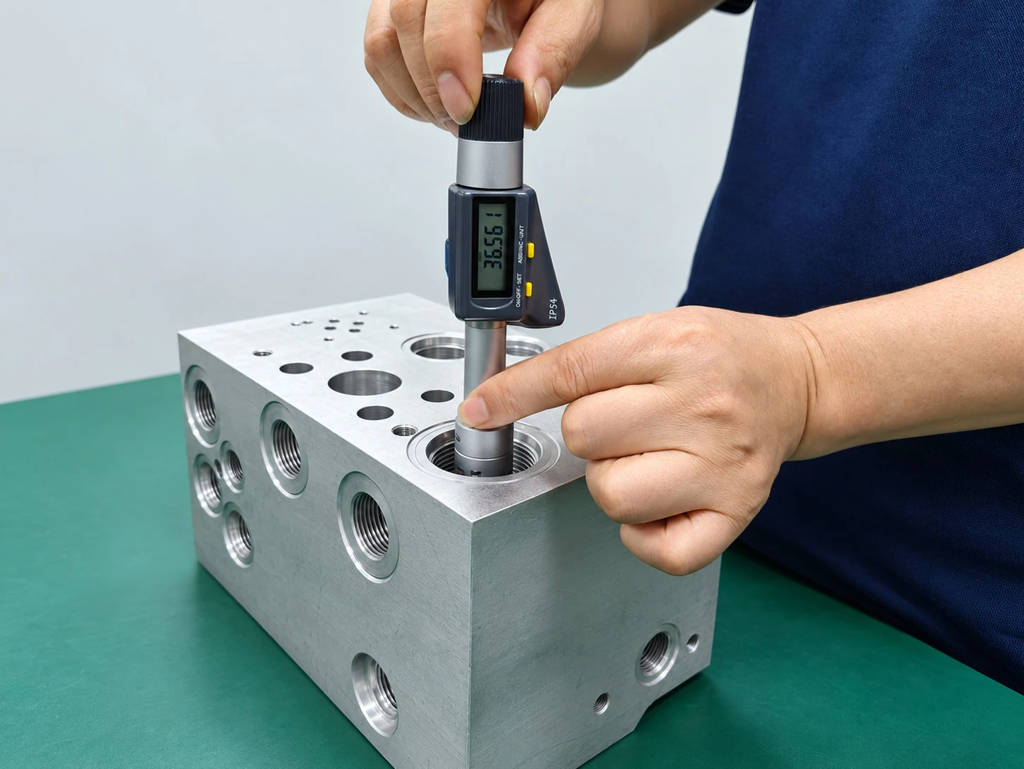
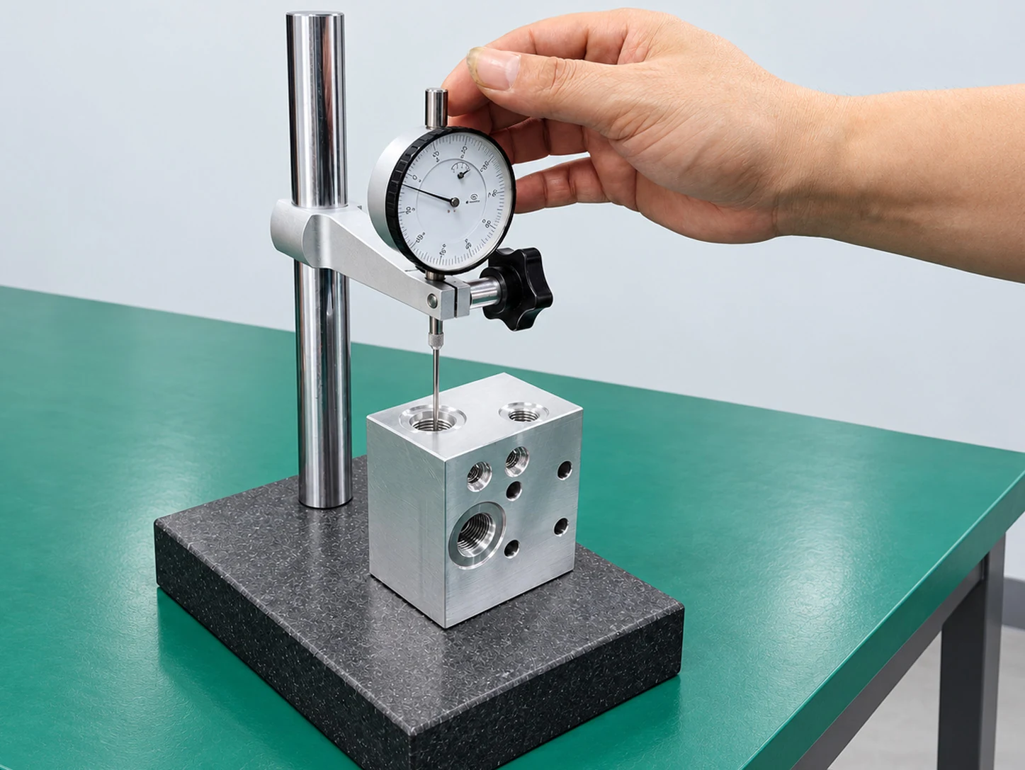
Normal inspection addresses the correct material, drawing dimensions, threads, specified bore geometry, sealing-surface roughness and burr removal. Concentricity, coaxiality or roundness must be checked as actually defined on the drawing, using an appropriate method.
Evidence for your receiving team
Material certificates and dimensional reports can be supplied. Agree any first-article package, CMM coverage, material certificate type or formal cleanliness report for the project, so the records answer the intended acceptance questions.
Machined manifold blocks are normally supplied without pressure or functional testing. Our normal acceptance work verifies manufacturing conformity; it does not validate the performance of an assembled hydraulic circuit.
Inspection methods and their scope Connect reports to the supplied partsQuestions about custom aluminum valve blocks
Which aluminum materials does Zhongwei commonly use?
6061-T6, 6082-T6 and 7075-T6 are common specifications in our manifold work. We also have machining experience with customer-specified 2017, 2024 and 6110. Material availability, exact temper, stock form and documentation are confirmed for each order.
Can 6082 replace 6061, or 2017A replace 2017?
Only after the specified requirements and proposed alternative have been reviewed and approved. 6061 and 6082 are different alloys; 2017 and 2017A have distinct registered compositions. Compare chemistry, temper, product form, mechanical requirements and finish rather than approving a substitution from a similar name.
Is an alloy number enough to order the material?
No. Include the exact temper, product specification, stock form and section requirements, with the required certificate. An AA number identifies an alloy reference; it does not by itself establish ASTM product compliance. For 6110 or 6110A, retain the exact designation and confirm the certificate basis.
Is 7075 always the better choice for cartridge valve threads?
No. Its higher strength can be useful in an approved design, but engagement length, surrounding material, assembly torque, loading and environment also matter. The design engineer must assess the complete interface; a stronger alloy is not a substitute for that assessment.
What pressure can an aluminum manifold withstand?
There is no single rating for all aluminum manifolds. Material condition, geometry, wall sections, passages, interfaces, temperature and load history affect the design. Share the specified operating conditions and approved material; we review the manufacturing requirements without assigning a universal pressure limit.
Can you guarantee identical anodized color across different alloys?
No. Alloy, condition, material batch and processing can affect appearance. We coordinate the finish requirements and can discuss sample approval for the intended material and process. Define visible surfaces and acceptable variation before production.
Can we start with a hydraulic schematic instead of a complete drawing?
Yes, a schematic can start the discussion. Include the valve list, cavity references, operating conditions and installation constraints. Material and interface decisions need to become an approved manufacturing definition before machining; complete manifold drawings are preferred.
What is normally verified before delivery?
The specified material and conformity to the drawing: dimensions, threads, required bore geometry, sealing-surface roughness and burr removal. Documentation is agreed for the project. Pressure and functional tests are not part of the normal machined-block inspection scope.
Send the drawing and the requirements that affect manufacture
Include the approved drawing revision, 3D model if available, exact alloy and temper, valve models and cavity references. Identify critical sealing surfaces, thread requirements, final finish and any appearance sample or inspection documentation requirement.
Tell us the sample and production quantities and whether the project is a new design or repeat part. We accept DWG, DXF, PDF and JPG drawings, and STEP, X_T, IGS and SLDPRT models by email or WhatsApp. A schematic with a valve list is also a useful starting point.
Prepare the project enquiryTechnical references: Kaiser Aluminum 6061 rod and bar data, 7075 rod and bar data, and Durox anodizing appearance guidance. These explain material and finish considerations; the approved project specification governs the supplied component.