
When the cylinder end also becomes a manifold
A valve-integrated cylinder end combines the cylinder’s structural connection with cavities and passages for specified hydraulic functions. It can place counterbalance, load-holding or other valve functions within the end component, reducing the need for a separate block and external connections where the cylinder design permits.
For a cylinder manufacturer, this creates a connected manufacturing problem: the structural interface, weld preparation, valve cavities and sealing features must work within the same geometry. Zhongwei reviews these features together and machines the component to the approved drawing and agreed delivery condition.
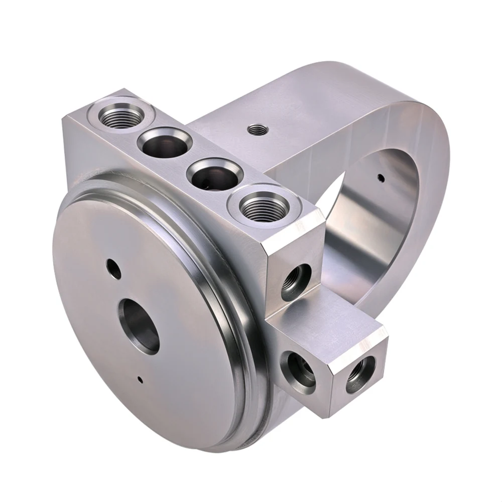

Our starting scope is the machined cylinder-end component. Welding, valve sourcing, assembly and completed-cylinder validation must be assigned explicitly within the project.
Control sealing surfaces in structural and medium-carbon steels
A correctly sized cavity still needs the specified surface condition at the seal. In Q355B and GB 45 steel, machining can leave tearing, built-up-edge marks or inconsistent roughness. This is a specialist part of Zhongwei’s cylinder-end work: we connect tool selection and finishing control to the particular sealing feature.
Control the finishing cut
Our process planning considers tool material and geometry, cutting speed and feed, finishing allowance and tool life. The approach is matched to the material condition and cavity geometry rather than copied from an easy-machining steel block.
Verify the specified surface
Identify the sealing diameter or face, required Ra limit and measurement access on the drawing. Surface-roughness verification is separate from dimensional measurement; the inspection plan needs both where the feature requires them.
Historical projects have achieved approximately Ra 0.8–1.6 μm on applicable key sealing surfaces. This is a reference for project discussion, not a blanket tolerance for every surface or material condition. We confirm the specified limit, measurement location and acceptance stage for the actual component.
Valve cavity tooling and machining Dimensional and surface inspectionChoose the material for the assembly, not pressure alone
Structural steel for cylinder ends — Q355B
For cylinder ends intended to join a welded structure, Q355B is part of our machining experience. Material requirements must cover the actual section, supply condition, structural duty and welding assessment alongside the valve-cavity requirements.
Medium-carbon cylinder-end steel — GB 45
GB 45 is a medium-carbon steel used in applicable cylinder-end projects. Its material and heat-treatment condition affect machining and finished properties. Welding needs its own assessment; it should not inherit the procedure used for a lower-carbon structural steel.
For European and US buyers, the table starts with familiar local references and identifies the Chinese grades used in these Zhongwei projects. It does not relabel Q355B as S355JR or A572 Grade 50, or GB 45 as certified C45/1045. If your drawing requires an EN or US grade, agree compliant sourcing and certificate requirements before ordering.
| European comparison reference | US comparison reference | Chinese grade used in these projects | Approval before substitution |
|---|---|---|---|
| S355JR — EN 10025-2 | ASTM A572/A572M Grade 50 | Q355B — GB/T 1591 | Structural-steel comparison candidates, not certified equivalents. Compare product form, section-dependent properties, chemistry, impact requirements, supply condition and welding suitability. Do not automatically substitute E355 or P355. |
| C45 / C45E — confirm the applicable product specification | SAE / AISI 1045 — confirm product specification and condition | 45 steel — GB/T 699 | Medium-carbon comparison references. Check chemistry, heat treatment, hardness and section properties. A welding assessment is required for the actual grade and joint; do not copy the Q355B welding route. |
C35E+QT and AISI 4140 may be relevant to other high-strength valve-block requirements. They are not automatic replacements for a weld-intended cylinder end. Pressure, wall thickness, fatigue, material condition and the joining route must be assessed together.
Material choices and cross-standard comparisonsBuild the component around the selected valve function
The customer’s circuit defines the function; the exact valve model and current cavity drawing define the machining interface. Similar threads do not establish interchangeability. We review cavity steps, sealing diameters, passage connections, remaining walls and installation access against those references.
Counterbalance and load holding
Identify the selected valve, pilot connections and cylinder-side passage requirements. Manufacturing review focuses on reproducing the approved interface and connections; load-control performance belongs in the circuit validation.
Pilot-operated checks and make-up functions
Specify the intended port relationships and cavity references. Adjacent passages, closures and assembly access need to remain clear in a compact end component.
Other circuit-specific functions
Relief, flow-control or other specified cartridge functions can be discussed from the schematic and valve list. Available space and material do not alone establish that a proposed function is suitable.
Agree the welding and machining sequence before release
A component checked before welding has only been verified in that condition. Welding can change dimensions and material condition, so the acceptance stage matters to the cylinder builder as much as the machining requirement. The actual sequence must follow the assembly design and the agreed welding procedure.
1. Define the delivery boundary
State whether Zhongwei supplies a machined component for subsequent welding or whether additional operations are being requested. Identify the responsible welding supplier, mating part and weld preparation.
2. Coordinate critical operations
Review whether critical features are finished before or after joining and any specified heat treatment. Consider access for subsequent machining and inspection; do not assume the same sequence suits every end design.
3. Set the final acceptance point
Identify which dimensions and sealing surfaces require checks after downstream operations, who performs them, and how the results connect to cylinder assembly approval.
Preheat, consumables, heat input and any post-weld treatment must come from the applicable welding assessment and procedure. The grade name or a pre-weld roughness result cannot establish the suitability of the finished welded assembly.
Manufacturing review before productionDelivered for welding: machined steel with oil preservation
For our Q355B and GB 45 valve-integrated cylinder ends and cylinder-head valve blocks intended for welding, the delivery route is machining followed by immersion in a no-clean rust-preventive oil and packing in a sealed, dust-protective PE bag. These components do not require plating, black oxide or phosphating for this supply route.
Avoid an extra oil-removal operation
The no-clean rust-preventive oil used by Zhongwei allows welding without a separate cleaning or degreasing step to remove the protective oil. Here, no-clean refers to the subsequent welding operation. Confirm the preservation route against the customer’s welding procedure; this statement does not apply to other protective oils or remove other weld-preparation requirements.
Protect the part before the next operation
Zhongwei uses approximately 3–6 months as an experience-based reference for this preservation route, subject to packaging and storage conditions. Dry storage helps maintain protection; moisture exposure, handling and damage to the bag or oil film can change the outcome. Agree the storage and transport requirements for the order rather than treating this reference as an unconditional rust-free period.
Customer feedback reported to Zhongwei describes parts protected with this oil and sealed in dust-protective PE bags that showed no rust after approximately one month of sea transport followed by more than one month in a warehouse. This is delivery experience for those conditions, not a controlled corrosion test or a guarantee for every shipment.
Record the agreed preservation route, packaging and intended storage period in the order requirements. The welding route and any later cylinder painting or finishing remain part of the customer’s assembly specification.
Cleaning and protected delivery Surface treatment and preservation routesUse the right evidence for each requirement
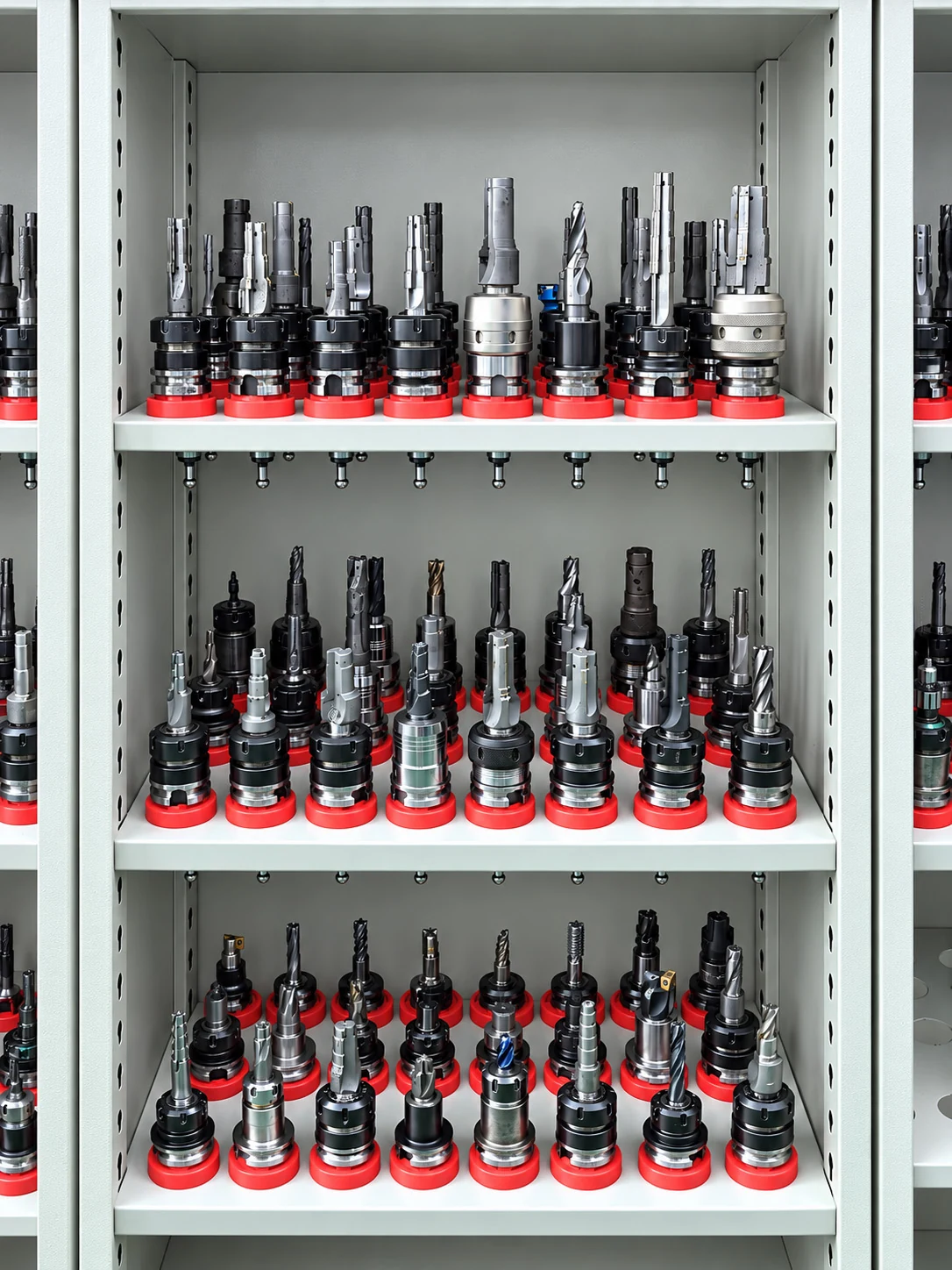
Tooling and manufacturing resources
Dedicated cavity tools and non-standard tooling development support our process planning. The component shown at the top of this page is a Zhongwei cylinder-end photograph; it illustrates the product type, not a certified material grade or measured roughness result.
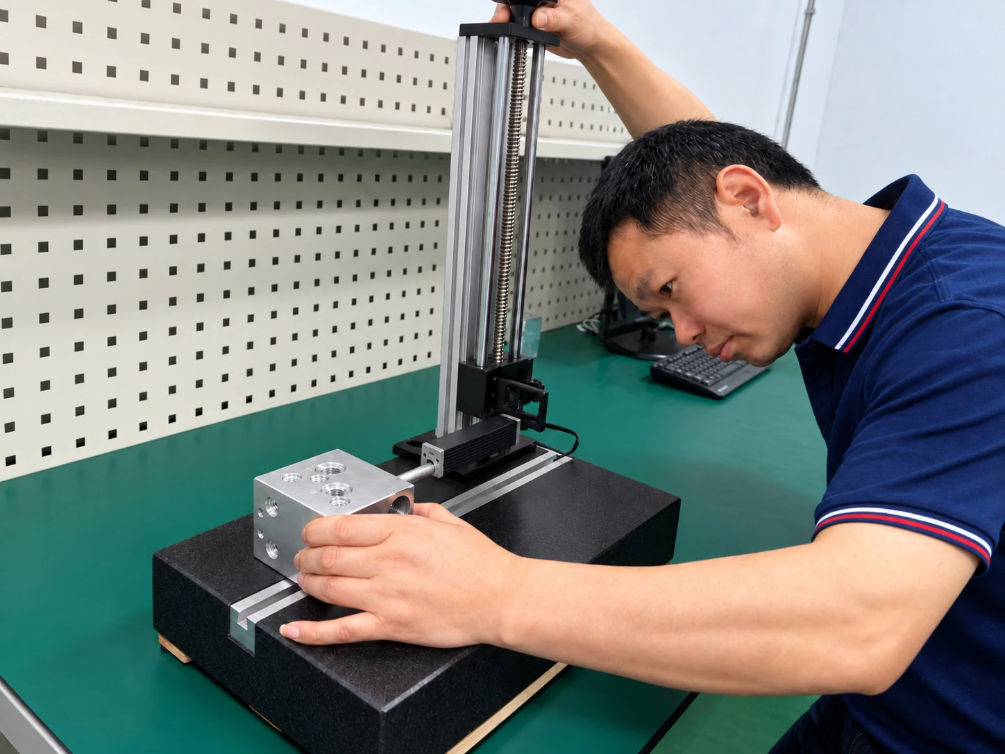
Checks tied to the drawing
Dimensional measurement, thread checks and roughness measurement address different requirements. Agree the critical features, inspection stage and records before ordering. A CMM result does not replace roughness, weld, leakage or functional acceptance.
Internal intersections also require deburring and cleaning, followed by clean handling and packaging. Machined manifold blocks are normally supplied without pressure or functional testing. Our inspection verifies the material and drawing requirements, including dimensions, threads, required bore geometry, sealing-surface roughness and burr removal. The design engineer determines material and design suitability for the operating conditions; completed-cylinder acceptance is outside normal machined-component supply.
Material documentation, first-article results and inspection reports can be discussed for the project. Records should identify the part revision and the condition actually inspected, so your team can relate the evidence to the assembly process.
Deburring, cleaning and packaging Inspection documents and traceabilityQuestions from cylinder manufacturers
Is a cylinder-mounted valve block the same as a valve-integrated cylinder end?
A cylinder-mounted valve block is a separate component attached to the cylinder. A valve-integrated cylinder end, or hydraulic cylinder head with integrated valve cavities, combines the end component’s structural interfaces with hydraulic cavities and passages in the same part. This page focuses on manufacturing that integrated component. The approved drawing defines the arrangement; a separate mounted block should be reviewed as its own manifold project.
Do welded cylinder-end blocks need black oxide or phosphating?
For our Q355B and GB 45 valve-integrated cylinder ends and cylinder-head valve blocks intended for welding, the delivery route is machining followed by immersion in a no-clean rust-preventive oil and packing in a sealed, dust-protective PE bag. These components do not require plating, black oxide or phosphating for this supply route.
Must the protective oil be removed before welding?
The no-clean rust-preventive oil used by Zhongwei allows welding without a separate cleaning or degreasing step to remove the protective oil. Here, no-clean refers to the subsequent welding operation. Confirm the preservation route against the customer’s welding procedure; this statement does not apply to other protective oils or remove other weld-preparation requirements.
How long does the oil protect the part against rust?
Zhongwei uses approximately 3–6 months as an experience-based reference for this preservation route, subject to packaging and storage conditions. Dry storage helps maintain protection; moisture exposure, handling and damage to the bag or oil film can change the outcome. Agree the storage and transport requirements for the order rather than treating this reference as an unconditional rust-free period.
Can you machine a cylinder end with a counterbalance valve cavity?
Yes, we can review a custom component combining the cylinder interface and a specified counterbalance-valve cavity. Send the valve model, current cavity drawing, schematic and component drawing. The selected circuit and completed-cylinder performance require their own approval.
Does the Ra 0.8–1.6 μm range apply after welding?
The historical range applies to applicable key sealing features in the condition covered by the project inspection. It is not an automatic post-weld guarantee. If acceptance is required after welding or heat treatment, identify that stage so machining and verification can be planned accordingly.
Does ordering the component include welding and cylinder assembly?
The starting quotation scope is the machined component and agreed records. Identify any welding, valve supply, assembly or testing you need, and confirm responsibilities and acceptance criteria before ordering.
Can Q355B or GB 45 be replaced by a local material grade?
A proposed substitute needs review against the required standard, chemistry, section properties, delivery condition and welding requirements. Similar grade descriptions are not proof of equivalence. Share the proposed specification and certificate requirements for discussion.
What is needed to move from the first sample to repeat orders?
Approve the sample against the agreed drawing, material condition and inspection stage. Record any changes arising from welding or assembly evaluation, then freeze the production revision, critical checks and supply scope for the repeat order.
Send the cylinder interface and valve requirements together
Send your project to tomas@zhongweimetal.com or WhatsApp +86 189 2574 6933. Include the component drawing and model, valve references, cylinder interface dimensions and the stage at which you need the part delivered.
Mark the features that matter
Specify material and condition, sealing-surface Ra requirements, critical dimensions, passage connections and weld details. Include the proposed machining, welding and heat-treatment sequence where defined.
Explain the supply requirement
State sample and repeat quantities, requested timing, required reports and any assembly or testing scope. If the main concern is surface quality, post-weld dimensions or a previous rejection, identify the affected feature.
DWG, DXF, PDF and JPG drawings, and STEP/STP, X_T, IGES/IGS and SLDPRT models can be sent by email or WhatsApp. A schematic and valve list can begin the discussion; approved manufacturing drawings are needed before production.
Prepare a complete project enquiry