

A schematic can open the discussion; a part definition enables machining
A hydraulic schematic communicates the intended circuit and connections. It does not, by itself, specify the manifold’s physical dimensions, material condition, cavity geometry, tolerances or final finish. Our review identifies what is known and what still needs a decision before the project can move toward manufacture.
Schematic available, block drawing incomplete
Send the current circuit and valve list, together with the intended installation and project requirements. We can identify missing interface references and manufacturing inputs, then agree who will prepare and approve the remaining documents.
Schematic and block drawing available
Provide both at the same revision status. Review their connection labels, valve references and interfaces together, and highlight any discrepancy or change that may affect the manufacturing definition.
Existing project with a new requirement
Identify what has changed, such as a valve reference, external connection or installation constraint. Keep the current approved documents distinguishable from proposed revisions so the review addresses the right configuration.
Bring the references that make the circuit unambiguous
Circuit and valve list
Provide a legible schematic with revision, component identifiers and connection labels. Add exact valve model or ordering references, quantities, relevant data sheets and current cavity or mounting drawings where available.
Operating and installation context
Describe the intended function, working fluid, pressure and flow requirements, temperature, duty conditions and installation envelope as defined by your engineering team. Identify external connections and access needed for assembly or service.
Project and supply scope
Tell us whether the required delivery is a machined block or includes separately agreed operations. Include quantities, material or finish requirements, requested records and the current stage of the project.
Missing details can be listed as open questions. An uncertain valve reference or an unresolved connection should remain visible as an item to confirm, rather than becoming an assumed machining instruction.
Prepare a schematic for project discussionMake connection questions explicit before layout work proceeds
The review focuses on the circuit information needed for the manifold project. We bring unclear references and connection questions back to your team, with the affected documents identified, so a manufacturing decision does not silently become a circuit-design decision.
| Review topic | What can be unclear | What to confirm |
|---|---|---|
| Component identity | A schematic symbol does not necessarily identify the exact valve or interface. | Match each relevant circuit identifier to the specified valve reference and its supporting documents. |
| Connection labels | An unclear label or inconsistent reference can leave the required connection open to interpretation. | Confirm the intended connections and how labels correspond across the schematic, valve documents and manifold drawing. |
| Pilot, drain and auxiliary connections | A connection shown in one document may be omitted or interpreted differently in another. | Raise any unclear routing or connection requirement for confirmation by the responsible circuit designer. |
| Operating states and settings | A drawing may not explain which operating state or setting the project requires. | Request the design team’s intended state, sequence or setting where needed to clarify the project. Do not infer safety performance from a symbol. |
| What belongs inside the manifold | Circuit components may be mounted on the block, installed elsewhere or connected externally. | Identify the intended integration boundary, external interfaces and the operations included in the manifold order. |
| Revisions and unresolved items | A revised circuit and an earlier valve list can describe different configurations. | Keep document status clear, list discrepancies and record the agreed response before releasing affected work. |
These are review topics, not a claim that every circuit has these issues. They do not replace the design engineer’s assessment of the complete hydraulic system.
Connect each circuit reference to a defined physical interface
Once a valve reference is confirmed, the manufacturing definition still needs the correct cavity or mounting interface. An external connection also needs its thread, sealing arrangement, position and related dimensions. A similar symbol or thread size is not proof of an interchangeable valve cavity.
Valve reference to cavity or mounting drawing
Use the exact specified model and current manufacturer reference. Resolve missing or conflicting interface information before selecting tooling and releasing the feature.
Connection requirement to manifold geometry
The approved layout must define actual passage connections, locations and access. Review geometry, wall sections, drilling, cleaning and inspection with the responsible design owner and manufacturing team.
The tooling photograph at the top of this page shows a Zhongwei workshop resource. It supports the manufacturing context; it does not establish compatibility with an unspecified valve or approval of a hydraulic circuit.
Valve cavity and hydraulic interface review Passage layout and cross-hole reviewAgree the documents and decisions needed for the next stage
The useful result of a review is a clear set of confirmed inputs, open items and responsibilities. Agree the form of the review feedback for the project; a complete manifold design package is not automatically included with a schematic enquiry.
1 · Clarify the circuit inputs
Confirm the relevant schematic revision, valve references, connection requirements and integration boundary. Record questions that still require a decision from your engineering team.
2 · Define the remaining work
Identify missing layout, interface, material, dimensional and inspection requirements. Agree who will prepare each document and who is responsible for its approval.
3 · Release the manufacturing definition
Bring the approved drawing, model and referenced requirements into alignment. Confirm the sample scope and applicable acceptance checks before the affected machining operations begin.
When only a schematic is available, quotation scope and assumptions need to reflect the information still missing. A manufacturing price and schedule can be confirmed against the agreed part definition and current production plan.
Review the drawing for manufacturability Connect sample approval to productionKeep circuit approval and component acceptance clear
Design and system responsibilities
The responsible design engineer determines circuit function, valve suitability, operating requirements, material and structural suitability, and the system validation needed. Zhongwei’s manufacturing review does not independently approve system safety, pressure capability or dynamic performance.
Manufacturing and acceptance responsibilities
We connect the approved part requirements to machining, cleaning and the agreed checks. Normal acceptance addresses correct material, specified dimensions and bore geometry, threads, sealing-surface roughness and burr removal.
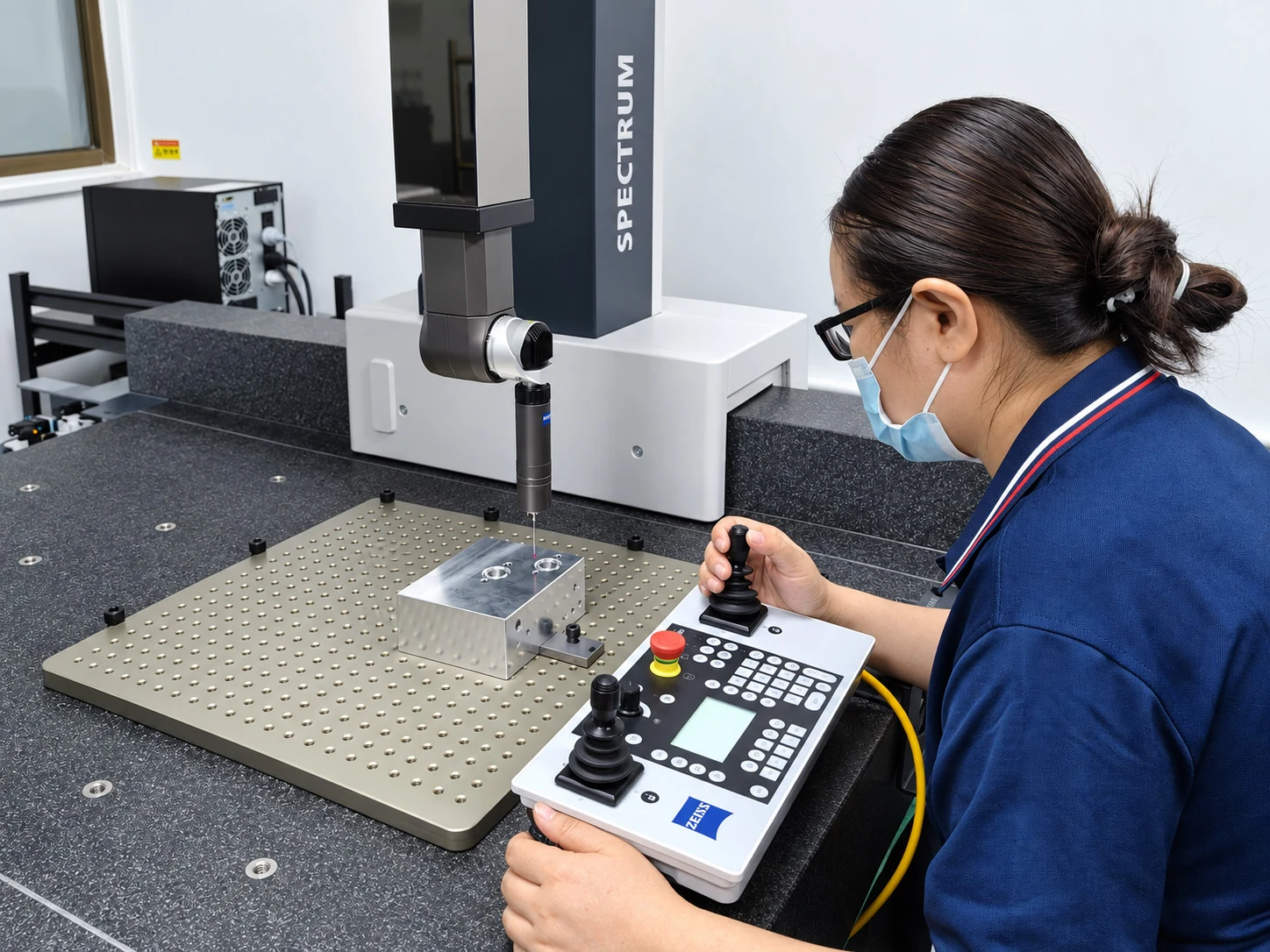
Pressure and functional testing are not routine checks for the machined block. Any additional design work, valve supply, assembly or testing must have an explicitly agreed scope. Material certificates and dimensional reports can be provided; first-article and CMM coverage are agreed by project.
Drawing-based inspection and its limitsQuestions about starting from a hydraulic schematic
Can I contact Zhongwei with only a hydraulic schematic?
Yes. Send the schematic and any available valve list, installation constraints and project requirements. We can discuss the missing information and next steps. Complete approved manifold drawings are preferred before machining.
Does a circuit symbol identify the cavity you should machine?
No. Confirm the exact valve reference and the applicable cavity or mounting drawing. A schematic communicates circuit intent; it does not automatically define every physical interface.
Can a review begin before every valve has been selected?
Yes, but unresolved selections remain open items. Interface details, manufacturing scope and timing may depend on the final approved valve references.
Does schematic review include a complete manifold design?
Not automatically. Agree the layout and drawing deliverables, design responsibility and approval process separately. The initial review identifies confirmed inputs and the work still needed.
Will you alter the circuit to simplify machining?
We can raise manufacturing concerns and discuss proposals. Changes to the circuit or approved part definition require the responsible design owner’s review and authorization before implementation.
What if the schematic and manifold drawing disagree?
Identify the affected connection or feature and the document revisions. Resolve which requirement is approved and update the affected information before releasing that work.
Does completing this review prove that the system will function correctly?
No. The review supports manufacturing preparation. Circuit approval and system validation remain separate responsibilities, and component dimensional inspection does not substitute for them.
Send the schematic and mark what is still undecided
Include the revision, valve list, available manufacturer references, intended connections, installation constraints and project quantities. Highlight any open valve selection, interface or layout question, and identify the person responsible for design decisions.
Send legible DWG, DXF, PDF or JPG drawings by email or WhatsApp. If a manifold model is available, include STEP, X_T, IGS or SLDPRT files and the corresponding drawing revision. A complete drawing package is preferred, but incomplete project information can start the conversation.
Project enquiry checklist