
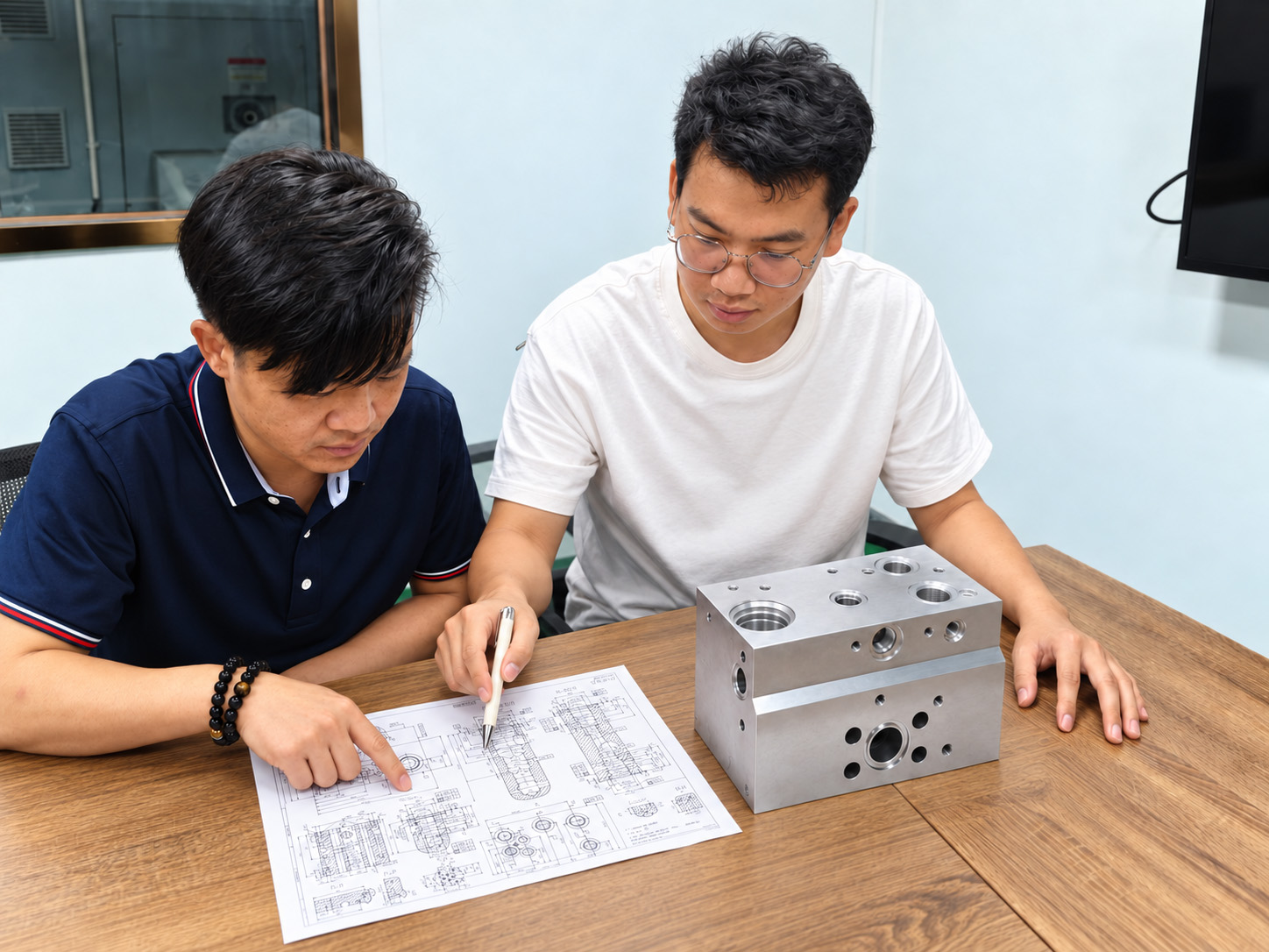
Start with one agreed definition of the part
A 3D model can show the shape while leaving important acceptance requirements undefined. A drawing can specify a feature that is difficult to reach, finish or measure. Design for manufacturability (DFM) review brings those requirements together before material, tooling and machining decisions are fixed.
Geometry and revision
Provide the current drawing and model, with datums, dimensions, geometric tolerances, threads, surface requirements and cavity references. Identify which documents are approved and which remain open for discussion.
Material and delivery condition
Specify the exact material grade and condition, final treatment, coated or protected areas, cleanliness and packaging requirements. Clarify which dimensions and surfaces must comply after treatment.
Project priorities
State sample and production quantities, the required delivery date and any known difficulty. Identify the functional features that must remain unchanged and the areas where a proposal can be considered.
Where documents disagree, we raise the discrepancy instead of choosing a tolerance, material or geometry without confirmation. A schematic can start a discussion; machining requires an approved part definition.
Drawing and tolerance guidanceReview the features that can create downstream difficulty
Our review connects the part geometry to machining, deburring, cleaning and inspection. The result should explain the concern and the decision needed, so your team can assess its effect on the approved design.
| Review area | Question to resolve | Review response |
|---|---|---|
| Datums and multiple setups | Can the part be located and supported while maintaining the specified relationships between faces? | Clarify datum interpretation, access and the relevant positional checks before choosing the setup route. |
| Cavities, ports and tool reach | Are the current interface references available, and can the required steps, threads and sealing areas be machined? | Confirm references and review tool access, dedicated tooling needs and finishing order. |
| Passages and intersections | Can the intended junction be reached, deburred and cleaned without changing neighboring features? | Flag access restrictions and proposed changes for review together with the passage and wall-section requirements. |
| Tolerance and surface scope | Do requirements distinguish critical functional areas from other surfaces? | Identify the specified features, measurement basis and final condition; discuss alternatives only where the design owner permits them. |
| Material and treatment | Do supply condition and finish requirements fit the proposed manufacturing sequence? | Review material availability, machining implications, treatment allowance and protection of critical surfaces. |
| Inspection access | Can the required characteristic actually be verified by the proposed method? | Agree accessible features, methods, reporting scope and any unresolved verification question before release. |
Valve compatibility is checked against the specified model and current cavity drawing. Material suitability, wall thickness and pressure design remain the responsibility of the design engineer; manufacturing review does not establish a universal pressure rating or minimum wall thickness.
Valve cavity and interface review Passage and cross-hole reviewExplain the manufacturing consequence before proposing a saving
Cost and lead time can be affected by additional setups, dedicated tools, difficult internal access, material condition, finishing operations and inspection effort. We discuss the relevant drivers for the actual component rather than promising a standard percentage saving.
Keep functional requirements explicit
A sealing diameter or mounting relationship may need a tighter requirement than a non-mating exterior surface. Ask the design owner to distinguish the necessary requirements; do not assume that a difficult tolerance can be relaxed.
Compare the complete route
A geometry change that simplifies machining may introduce another closure, treatment or inspection requirement. Consider those consequences together before deciding whether the proposal benefits the part.
Consider the order pattern
A prototype and a recurring batch may justify different tooling or workholding preparation. Review preparation effort, quantities and expected repeat orders while keeping the accepted component requirements the same.
If the design must remain unchanged, the discussion focuses on feasible process and inspection options. Any alternative material, tolerance, finish or geometry requires approval before it becomes a production instruction.
Dedicated tooling and preparation Sample and batch production planningExamples of questions worth resolving before machining
These are illustrative review situations, not customer case studies or measured results.
A model and drawing show different depths
Question: which definition governs this feature? Review the reference, intended connection and neighboring geometry. Record the approved depth and update the affected documents before machining.
A critical internal edge has restricted access
Question: how will that edge be finished and checked? Review the process route and available openings. If a design change is proposed, its effect on the circuit and structure goes back to the design owner.
A close-fitting bore also needs a coating
Question: does the tolerance apply before or after treatment? Confirm final size, surface requirements and treated areas, then align machining allowance, processing and inspection with that condition.
The useful output is a resolved requirement and an agreed route, rather than a general statement that the model is “manufacturable.”
Finish requirements and final dimensionsTreat verification as part of manufacturability

Plan checks for the actual feature
The CMM photograph at the top of this page shows a Zhongwei inspection resource. The method used still needs to suit the datum, tolerance, geometry and access of the feature being accepted. Accessible measurements cannot automatically prove every hidden internal surface.
Resolve limitations before release
If the proposed check cannot establish a critical requirement, identify the gap while the inspection plan can still be discussed. Agree the method, stage and evidence needed instead of treating a generic report as proof of the whole component.
Normal verification covers the specified material and drawing conformity, including applicable dimensions, thread-gauge acceptance, bore geometry, sealing-surface roughness and burr removal. Pressure and functional testing are not routine checks for the machined block. Material certificates and dimensional reports can be provided; first-article and CMM coverage are agreed for the project.
Inspection methods and their scope Project records and traceabilityTurn review comments into an approved manufacturing basis
Identify the concern
Reference the drawing revision and affected feature. Explain the manufacturing or verification issue and distinguish a missing requirement from a proposed improvement.
Discuss the response
Describe the proposed route or change, the reason for it and the requirements it could affect. Identify questions for the customer or responsible design engineer.
Record the decision
Keep the approved response linked to the current part definition. Resolve open manufacturing questions and confirm the required checks before releasing the affected work.
A review recommendation is not authorization to alter the customer’s design. DFM support does not replace hydraulic circuit design, structural approval or system-level validation. Those responsibilities and any additional engineering scope must be agreed separately.
For an existing manifold, provide the current approved documents and any known manufacturing or assembly concern. Earlier samples and records can help discussion, but the current requirements remain the basis for the order.
Questions about manifold drawing and DFM review
Can you review a model without a complete drawing?
Yes, it can support an initial discussion of geometry and access. Material condition, datums, tolerances, cavity references, finish and acceptance requirements still need to be defined before manufacture.
Will you change the design to make it easier to machine?
We can identify concerns and propose alternatives. Changes to the approved geometry, material, tolerance or finish require customer authorization before implementation.
Does DFM review mean you will reduce our tolerances?
No. Review clarifies which requirements apply and how they can be achieved and checked. Any suggested change must preserve the design intent and be approved by the responsible design owner.
Can a review guarantee a lower price or shorter lead time?
No fixed saving is promised. The effect depends on the actual geometry, material, tooling, quantities, finishing and inspection scope. A proposal should explain its manufacturing consequences so the options can be compared.
Does a manufacturable part automatically meet the required pressure rating?
No. Material, structure, wall sections and duty conditions need the responsible engineer’s assessment. Manufacturing feasibility and drawing conformity do not independently establish hydraulic performance.
Can you review an existing manifold with recurring problems?
Yes. Send the current documents and describe the observed issue, affected feature and available inspection information. Authorized reference samples can help; a sample alone does not establish every tolerance or material requirement.
What should be agreed before the first sample?
Confirm the approved part definition, resolved review comments, material and finish, sample quantity, critical checks, required records and customer review steps. Identify any remaining questions before releasing the affected operations.
Send the drawing and tell us what is difficult
Share the current drawing and model, exact material and condition, finish, cavity references and quantities. Mark the features or cost drivers you want reviewed, explain any recurring issue, and identify requirements that must remain unchanged.
Complete manifold drawings are preferred; a schematic can start the discussion. Send DWG, DXF, PDF or JPG drawings and STEP, X_T, IGS or SLDPRT models by email or WhatsApp. Indicate which documents are approved and which are still being developed.
Prepare the project enquiry