
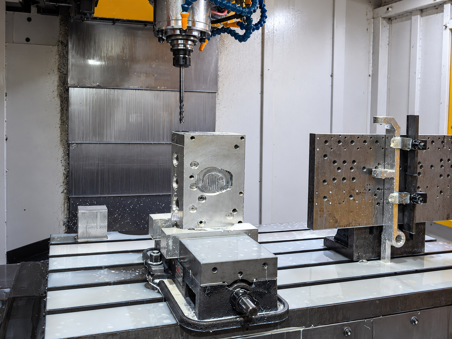
The difficult work is inside the compact block
To reduce the size of a hydraulic manifold, a design may route passages at an angle, including compound-angle directions, through a dense arrangement of cavities and other drillings. Machining the outside faces is only part of the task. The internal holes must reach the intended junctions while meeting the specified dimensions, geometry and surface requirements.
Reach the intended connection
Position, direction and depth together determine where a drilling meets another passage. The entrance can appear correct while the internal relationship still needs verification.
Preserve bore quality through intersections
Deep passages and intersecting cuts need attention to tool condition, cutting stability and chip removal. The hole must meet its specified accuracy and surface finish as well as make the required connection.
Control the edges created by machining
Each junction can create an internal edge that is difficult to reach later. Experienced process planning considers how the edge is formed, how burr formation can be reduced and how remaining burrs will be addressed.
Zhongwei’s manifold machining experience includes these connected difficulties. We assess the actual geometry and requirements rather than using the number of exterior faces as the measure of machining complexity.
Review the internal passage layoutDifferent intersections create different machining conditions
Right-angle cross holes
Even perpendicular passages can be difficult when intersections are numerous, deep or close to valve features. Drilling order, chip removal and access to the resulting internal edge all need consideration.
Oblique intersections and angled holes
An inclined drilling or non-perpendicular junction changes the entry, crossing or breakthrough conditions. Review the actual angle, intersecting diameters and depth together with the tool approach.
Compound-angle passages
The hole direction is inclined in two planes. Both angular components, the entry position and the depth must remain tied to the drawing datums so the drilling reaches the intended internal junction.
Breakout edges also need attention: a drilling may break into an existing passage or meet an edge with partial cutting engagement. Here, the drawing and model define the actual geometry; “breakout” is a description of the cutting situation, not a substitute for a feature specification.
Hole position, diameter, depth, specified geometric accuracy and surface roughness are considered together. Roughness requirements apply to the identified surfaces on the drawing; a sealing-surface requirement is not automatically applied to every internal passage.
Connect the workholding plan to the drawing datum system
For an angled or compound-angle passage, the setup must establish the drilling direction as well as the entry location. Zhongwei reviews the drawing datums, angular definitions, locating surfaces, tool access and support. Each orientation remains related to the same approved part coordinates.
Establish the reference features
Identify which surfaces or features locate the part and when they become available in the process. Clarify ambiguous datum or dimension references before choosing the machining route.
Locate, support and protect
Plan contact and support around the component geometry, cutting access and surfaces that must remain undamaged. Consider whether clamping could affect the feature being machined or the condition in which it will be checked.
Relate the next setup to the same part
Define how the next orientation is located and checked. Machine coordinates and setup references must support the drawing relationships rather than treating each face as a separate component.
The number of setups and the machining approach are chosen for the actual geometry and requirements. We do not promise that every manifold is completed in one clamping or requires the same machine configuration.
Review datum, access and manufacturing questionsConnect the difficult geometry to an appropriate process
Experience matters in deciding how these conditions interact. A route that works for a straight, uninterrupted hole cannot simply be assumed to suit a deep angled passage crossing several other holes.
| Control point | Risk to address | Manufacturing response |
|---|---|---|
| Hole direction and location | An incorrect angular or positional reference can move the internal junction away from its intended location. | Relate entry position, both angles where applicable, and depth to the drawing datums; define the relevant setup and feature checks. |
| Deep reach and chip removal | Long tool reach and retained chips can make the required geometry and bore surface more difficult to maintain. | Review reach, support, tool condition and chip evacuation for the actual material and passage. |
| Crossing an existing passage | Cutting engagement changes at a junction, with implications for the tool, bore condition and internal edge. | Consider intersecting geometry and drilling order together; select the crossing strategy for the operation. |
| Inclined entry and breakout | Partial or uneven engagement can create a more demanding cut and an internal edge requiring attention. | Review entry preparation, tool geometry and local cutting conditions against the actual feature, then check the resulting condition. |
| Accuracy and surface finish | A connected hole can still fail its specified diameter, geometry or roughness requirement. | Coordinate drilling and any required finishing with the applicable dimensional and surface checks; do not accept connection alone as proof of conformity. |
| Later cavity work and deburring | A later operation can create new burrs or affect a finished sealing feature. | Plan drilling, cavity finishing and burr removal as a connected route, protecting the final approved geometry. |
Achievable tolerances depend on the part geometry, material condition, setup, feature and verification method. We confirm them against the drawing rather than advertising one positional accuracy for every manifold.
Reduce burr formation through the machining route
Burr control starts while planning how the intersection will be cut. Zhongwei considers the order of intersecting holes, tool geometry and condition, entry preparation, cutting conditions at the junction and chip evacuation. The aim is to reduce burr formation while preserving the required hole quality and access for subsequent work.
Choose the order of intersecting operations
Assess which hole is formed first and what happens when the later cut crosses it. Include nearby cavity and sealing features, rather than choosing a sequence only for the shortest cycle time.
Match tooling and cutting conditions
Consider edge condition, tool support and the change in engagement at entry, crossing and breakthrough. Select the route for the material and geometry; a fixed feed change or drilling order is not a universal solution.
Finish and verify the internal edges
Plan access for removing remaining burrs without changing the specified feature. Follow with appropriate cleaning and checks. Reducing burr formation does not eliminate the need for deburring and inspection.
Technical background: Sandvik Coromant on cross-hole and inclined-surface drilling. Tool-specific guidance is assessed for the actual operation; it is not a universal recipe or a claim that a particular tool is used on every Zhongwei project.
There is no universal sequence for all manifolds. Proposed changes to geometry, datums, tolerances or finish need customer approval before they become manufacturing instructions.
Deep-hole and cross-hole machining Valve cavity tooling Internal deburring and cleaningCheck relationships as well as sizes
Match the method to the requirement
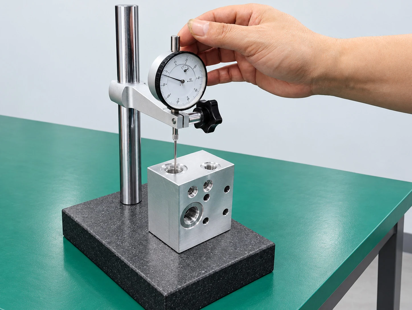
Verify applicable sizes, positions, orientations and surface requirements against the specified datums. The CMM photograph at the top of this page shows an inspection resource; actual coverage depends on the feature, access and agreed measurement plan.
Use checks at the relevant stages
Setup and in-process checks can identify an issue before more work is added. Final verification addresses the agreed delivery condition. An individual thread-gauge or diameter result does not substitute for a specified positional check.
Some internal features may not be accessible to the proposed measurement method. Resolve critical verification questions before production. CMM measurements do not automatically prove every hidden passage, full-depth bore condition or sealing-surface roughness.
Normal acceptance verifies the specified material and drawing conformity, including applicable dimensions and bore geometry, thread-gauge acceptance, sealing-surface roughness and burr removal. Pressure and functional testing are not routine checks for the machined block. Material certificates and dimensional reports can be provided; first-article and CMM scope are agreed by project.
Inspection methods and their limitsKeep the approved setup requirements available for the next order
A repeat order needs the same clarity about datum references, orientation, tooling, inspection and finish as the first batch. Carry the released requirements forward, and review any change that affects the manufacturing route or acceptance.
Control the part definition
Confirm the current drawing and model revision, exact material condition, finish and critical features. A familiar part number is not a substitute for checking the released requirements.
Review setup or process changes
Assess the effects of a changed fixture, tool or operation sequence on the relevant features and checks. Customer notification and approval follow the agreed requirements for the change.
Preserve the delivery condition
Connect accepted parts to the required records, identification and packaging. Protect mounting and sealing surfaces through final handling and shipment.
Questions about complex manifold passage machining
Why does a compact manifold need more than ordinary face machining?
Its internal network can combine deep cross holes, oblique intersections, angled entries and compound-angle directions. Position, direction, depth, bore quality and the resulting internal edges must be controlled together.
How do you reduce burrs at difficult intersections?
Review drilling order, tool geometry and condition, entry preparation, cutting conditions and chip removal together. The route is selected for the actual junction and material. Remaining burrs still require appropriate removal, cleaning and inspection.
Must every manifold be machined in a single setup?
No. The route depends on geometry, access, material and required feature relationships. The important point is how each operation relates to the approved datums and how the required geometry is verified.
Does passing the bore diameter check prove its location is correct?
No. Diameter and location are different characteristics. A positional or orientation requirement needs an appropriate check against the specified datum system.
Can you quote before the datum requirements are clear?
An initial discussion can begin, but unresolved datums or tolerances can affect workholding, inspection, cost and timing. Identify and resolve those questions before the affected manufacturing work is released.
What tolerance can you hold across different faces?
It must be confirmed for the actual feature and part. Send the drawing, material condition, datum system and final treatment requirements so machining and measurement feasibility can be reviewed together.
Can a later drilling affect an already finished valve cavity?
It can affect the intersecting edge or surface condition. The process route needs to connect passage machining, cavity finishing, deburring and the applicable final checks.
What changes on a repeat order require review?
Review changes that can affect the part definition or its acceptance, including material, datum, geometry, finish and relevant setup or process changes. The checks and approval scope depend on the change and the agreed project requirements.
Send the drawing with the important relationships identified
Include the current model and drawing revision, material and condition, datums, hole directions and depths, specified accuracy and roughness, cavity references and final finish. Highlight compound-angle passages, dense intersections, breakout edges or known burr problems, and state sample and batch quantities.
Complete manifold drawings are preferred; a schematic can start the discussion. Send DWG, DXF, PDF or JPG drawings and STEP, X_T, IGS or SLDPRT models by email or WhatsApp.
Prepare the project enquiry