
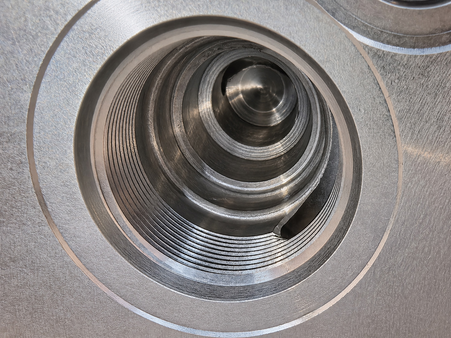
Make the intended connections clear before reviewing the drillings
A passage that looks connected in one view may still be unclear in depth, position or relationship to a valve cavity. We review the internal geometry against the controlled part definition, identifying manufacturing questions while there is still time to resolve them before production.
What connects to what?
Provide the schematic or connection information, with consistent port and valve labels. Identify pressure, return, working and any pilot or drain paths as applicable. The design owner resolves contradictions between the circuit information and the manufacturing documents.
Where does each drilling go?
Supply the 2D drawing and 3D model where available, including passage diameters, locations, depths, datums and relevant sections. Clarify whether a depth refers to the drill tip or the full-diameter portion wherever that distinction affects an intersection or nearby feature.
What must remain intact?
Identify critical sealing regions, neighboring cavities, mounting holes, minimum wall requirements and closure details. Include the material and condition. These constraints belong in the review alongside the intended passage route.
A schematic can begin the discussion, but it does not fully define the geometry to machine. Complete manifold drawings are preferred. Any missing or conflicting requirement must be resolved in the approved manufacturing definition.
Look at the geometry hidden between the outside faces
The review brings the intended connections and the regions that must stay separate into the same discussion. This helps identify places where a small dimensional or sequencing issue could create expensive rework later.
| Feature | What can go wrong? | Review and manufacturing action |
|---|---|---|
| Intended intersection | The specified drillings may stop short or overlap less than the design requires. | Review their positions, diameters, depth definitions and tolerances together. Clarify the required intersection geometry before setting the drilling operations. |
| Unintended breakthrough | A drilling or its tip may reach an adjacent cavity, thread or passage that should remain separate. | Review the full drilling envelope and neighboring features. Raise insufficient clearance or undefined limits with the design owner. |
| Long or opposed drillings | Hole deviation can affect where passages meet and the material remaining around them. | Consider entry conditions, reach, datum relationships and drilling direction. Agree how critical geometry can be checked for the actual part. |
| Cross-hole edge | An internal burr may remain at a junction that is difficult to reach after later operations. | Identify the intersection early and plan machining order, deburring access and the appropriate check without damaging a sealing feature. |
| Blind region or closure location | Chips or cleaning residues may be difficult to remove, or a specified closure may restrict later access. | Review the access and exit paths, plug details and operation sequence. Confirm which closures, if any, are included in the supplied component. |
Wall requirements depend on the material, structure, duty and applicable design criteria. We raise manufacturing concerns for review; the responsible engineer determines structural adequacy. A visible gap in a CAD model is not, by itself, evidence that a pressure boundary is adequate.
Review the valve cavities and connection interfacesPlan passage machining together with cavity finishing
Entry, reach and chip removal
Review whether the tool can enter and reach the required geometry with a suitable setup. Material condition, passage dimensions and interrupted cuts at existing holes affect the drilling plan. Chip evacuation must be considered throughout the operation.
The order of intersecting features
A later cross-drilling operation can create an edge or burr inside a previously machined cavity. Plan the sequence so that intersection work, deburring and final sealing-surface requirements remain compatible. The appropriate route depends on the actual material and geometry.
One datum system across several faces
Use the drawing datums to relate drillings made from different faces. Opposed drillings and cross-face features need their specified positional relationship maintained through setups, rather than being assessed as unrelated holes.
Zhongwei connects the passage review to multi-face machining, tooling preparation and experienced deburring. Project-specific drilling depths, reach and inspection access are confirmed from the part; we do not use a single depth or length-to-diameter claim for every manifold.
Drilling context: Sandvik Coromant guidance on cross-hole and irregular-surface drilling describes tool-dependent issues with intersections and chip evacuation. The process is selected for the actual operation.
Deep-hole and cross-hole machining Tooling and finishing preparationProvide a route to reach burrs and remove the residues
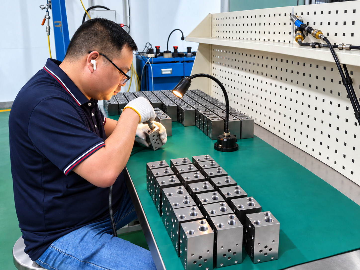
Access to the critical junction
Identify which opening gives access to each intersection and whether later machining or a closure changes that access. Experienced manual work can be important for complex, small-batch manifolds. The method must protect sealing surfaces and the approved passage geometry.
A path out of the block
Cleaning needs a way to reach relevant surfaces and remove loosened material. Review blind regions, branch passages and the required delivery condition. Any included plug installation or subsequent treatment must be considered in the sequence.
Deburring, cleaning and formal cleanliness verification answer different questions. If measured particle-cleanliness evidence is required, agree the method, sample, limits and reporting scope. Zhongwei can coordinate project-specific SGS testing to ISO 16232; routine cleaning is not a certificate of a particle limit.
Verification reference: ISO 16232 — component cleanliness inspection. Apply an agreed specification and inspection scope for the component.
Deburring, cleaning and packaging controls Third-party cleanliness verificationResolve layout concerns with the design owner
When a passage creates a manufacturing or access concern, the useful next step is to identify the affected feature and the decision needed. A manufacturing suggestion becomes a production instruction only after the required approval and document update.
An intersection sits close to a sealing region
Mark the relationship that needs review and discuss the effect on cavity finishing and burr-removal access. The design owner decides whether a position, diameter or other requirement can change.
The planned closure removes cleaning access
Clarify the closure specification and supply scope. Review the sequence before closure, or discuss whether an approved access change is required. Do not add an opening or substitute a plug without approval.
The drawing leaves a depth ambiguous
Identify the relevant datum, full-diameter depth, drill-tip envelope and intended intersection. Obtain a clear dimensioning basis rather than inferring a depth from a schematic line or one model view.
These are illustrative review situations, not customer case studies. Retain the approved revision and decision with the manufacturing information so the resolved issue remains clear at the machine, during inspection and on repeat orders.
Revision control and part documentationAgree what can be checked before the part is released
Specify the critical geometry
Identify the required bore sizes, drilling depths, locations and geometric tolerances on the controlled drawing. Relate them to the specified interfaces and material. Measurement methods must suit the access and the feature being assessed.
Address limited access early
A CMM or an external bore measurement cannot establish every hidden internal condition. Where a critical feature cannot be reached by the proposed method, agree an appropriate verification approach before production. Do not leave that question until the finished part is ready to ship.
Keep different evidence separate
Dimensional reports address their stated features. Material records address the supplied material. Burr-removal checks and any formal cleanliness result have their own scope. Agree the required documentation and its link to the supplied batch.
Normal acceptance verifies the specified material and conformity to the drawing, including the required dimensions, threads, bore geometry, sealing-surface roughness and burr removal. Pressure and functional testing are not routine checks for the machined block.
This manufacturing review does not establish circuit pressure drop, flow capacity or system performance, and does not include a CFD or structural-analysis deliverable unless separately agreed and supported. Hydraulic design and performance validation remain with the responsible design team.
Drawing-based inspection and its limitsQuestions about internal passages and cross holes
Can you start from a hydraulic schematic?
Yes. Include a valve list, port labels, operating conditions and installation constraints. The schematic helps identify intended connections; the approved part drawing and model need to define the passage geometry for manufacture.
Does a connected CAD model prove the passages will be correct?
It defines nominal geometry, but the drawing requirements, drilling direction, depth interpretation, tolerances and process must also be addressed. The manufactured part needs verification against the approved definition.
How do you handle minimum wall thickness?
Identify the surrounding features and the specified wall requirements, and raise unclear or conflicting geometry with the design owner. There is no universal minimum for every material, pressure duty and manifold layout. Structural acceptance belongs to the responsible design engineer.
Can a difficult intersection simply be drilled deeper?
Only if the resulting geometry is reviewed and approved. Increasing depth can affect nearby passages, cavities or the material left at the end of the drilling. Resolve the actual intersection and drill-tip envelope before changing the instruction.
Is cleaning enough to remove a burr at a cross hole?
Cleaning and burr removal are separate process questions. Plan a suitable deburring method and access to the junction, then remove the resulting residues. A cleaning operation alone does not establish that an attached burr has been removed.
Can you guarantee a particular flow rate or pressure drop after this review?
The review described here addresses manufacturability, passage geometry and access for cleaning and verification. Flow capacity and pressure drop depend on the complete hydraulic design and operating conditions; they are not established by this review.
What should be resolved before production?
The controlled drawing and model revisions, connection and depth definitions, critical surrounding geometry, approved changes, process access and inspection scope. Confirm any required written review record and delivery documents for the project.
Send the layout and highlight the passages that concern you
Provide the current 2D drawing, 3D model if available, schematic or connection information, material and condition, cavity references and critical wall or sealing requirements. Highlight uncertain intersections, difficult access, closure details and any special inspection or cleanliness requirement.
Include sample and production quantities. We accept DWG, DXF, PDF and JPG drawings, and STEP, X_T, IGS and SLDPRT models by email or WhatsApp. Complete manifold drawings help turn the review into a clear manufacturing discussion.
Prepare the project enquiry