
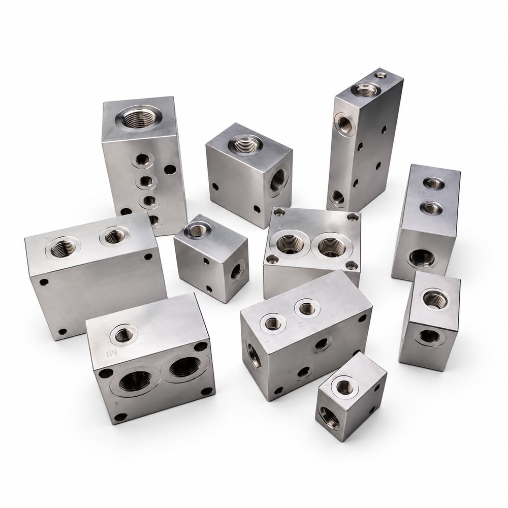
The thread holds the connection. The specified interface defines the seal.
A fitting may appear to engage while the sealing arrangement is still wrong. A valve can share a familiar mounting size while requiring different pilot or drain details. Defining the complete interface before machining helps avoid reworking a finished block at assembly.
Connection identity
Record the interface family, standard and edition, complete size designation and mating fitting or valve reference. Nominal sizes from different systems do not establish interchangeability.
Sealing geometry
Locate the actual sealing region: an O-ring housing, a specified face, a seat or a thread-sealing connection. Include the required geometry and surface condition for that arrangement.
Installation context
Check fitting orientation, wrench access, valve envelope and bolt access against adjacent ports and components. A correct isolated interface can still be difficult to assemble in the finished layout.
This guide concerns external connections and valve mounting surfaces. Screw-in cartridge valve cavities require their own controlled references.
Read the cartridge valve cavity guideCompare the connection family before comparing the size
| Port family | Reference basis | What the drawing must clarify |
|---|---|---|
| BSPP / G parallel-thread ports | ISO 228-1 thread references; ISO 1179-1 for the applicable port geometry. | Specify the intended stud-end and sealing arrangement. A G thread designation alone does not define the complete seal or spotface. |
| Metric O-ring ports | ISO 6149-1 ports with metric threads and an O-ring housing. | Specify the full metric size and port reference. A generic metric tapped hole does not establish the required sealing geometry. |
| SAE O-ring boss (ORB) | SAE J1926/1 ports with unified threads and O-ring sealing. | Record the complete port designation and mating stud end. A similar thread on another connector does not make it an ORB interface. |
| NPT pipe-thread connections | ASME B1.20.1 for NPT dimensions and gauging. | Identify NPT explicitly, with size and the required thread acceptance. Follow the selected fitting’s sealing and installation instructions; do not substitute another pipe-thread family. |
| BSPT / ISO 7-1 connections | ISO 7-1 thread designations for joints made pressure-tight on the threads. | Specify the exact internal and external thread designations and the approved mating arrangement. BSPT and NPT are distinct; “pipe thread” is incomplete. |
| Four-screw flange connections | SAE J518/1 Code 61 or SAE J518/2 Code 62, as specified. | Confirm code, size, mating flange, bolt pattern, seal arrangement and face requirements. A shared nominal size does not make Code 61 and Code 62 interchangeable. |
This table identifies reference families; it is not a dimensional interchange chart or a pressure-rating table. The responsible engineer selects the connection for the material, structure and operating conditions. Use the applicable standard edition and fitting documentation to define the actual part.
A valve mounting size is the start of the face definition
ISO 4401 addresses mounting surfaces for four-port directional control valves. Familiar NG, CETOP or NFPA size descriptions help identify an interface, but the released drawing must still identify the exact pattern and the selected valve’s requirements.
Pattern and orientation
Confirm port positions, mounting holes and any locating features from the specified view and datum. Keep P, T, A and B labels consistent with the selected valve and circuit; check additional pilot or drain connections where required.
Face and sealing features
Specify the applicable flatness, roughness and local sealing details. Establish which component carries the seal or groove from the mating drawings. Do not add a groove or change a face based only on a familiar valve size.
Mounting and clearance
Define bolt threads, usable engagement and the surrounding envelope. Check installation access and any stacked-valve arrangement, including the approved fastening requirements.
Hole-pattern conformity does not approve the circuit, the installed valve or the assembly load. The project’s responsible engineering team confirms those requirements; Zhongwei manufactures the block to the approved definition.
See power unit manifolds and valve platesMake each port and mounting face unambiguous on the drawing
| Drawing item | Information to provide | What this prevents |
|---|---|---|
| Interface designation | Standard and edition, full size, thread designation or mounting-pattern code, plus the selected mating component. | Avoid a generic note such as “SAE port” or “BSP thread”. |
| Location and orientation | Drawing view, face, datum, port label, positions and orientation of relevant features. | Prevent a mirrored pattern or a correctly sized port on the wrong face. |
| Seal and surrounding face | Required seal form, housing, spotface or seat; applicable dimensions, finish and geometric controls. | Give the inspector a defined sealing feature to check separately from the thread. |
| Depths and internal connection | Usable thread depth, drilling depth, passage connection and the approved surrounding geometry. | Distinguish thread engagement from drill depth and identify relevant intersection risks. |
| Assembly envelope | Fitting or valve dimensions, wrench or bolt access and constraints from neighbouring components. | Resolve access conflicts while the drawing can still be changed. |
| Delivered state and records | Material and condition, finish, masking where specified, final acceptance stage and requested records. | Verify the delivered interface against the agreed drawing after the relevant processing steps. |
When the model, drawing and component data sheet disagree, identify the affected interface and obtain an approved resolution before machining it. Do not fill the gap by selecting a familiar shop standard.
Define drawing requirements and tolerancesResolve an incomplete label before it becomes a machined feature
“G thread” without a seal detail
Clarify the mating fitting and applicable port geometry. The thread callout does not explain every face, seal or clearance requirement.
“SAE connection” without its family
Confirm whether the drawing means ORB, a flange connection or another interface. Keep the manifold-side and hose-side ends of an adapter separate in the specification.
“Same valve size” without the mounting drawing
Confirm the exact valve reference, face pattern, orientation and additional connections. A nominal size does not resolve pilot, drain or installation details.
These are illustrative specification gaps, not reported customer failures. Record the answer in the released drawing set so machining, inspection and receiving teams work to the same requirement.
Request an interface reviewMatch the inspection method to the interface feature
Thread acceptance
Use the gauges and acceptance method appropriate to the specified thread standard. Parallel and tapered threads require the relevant gauging approach; a mating fitting trial does not replace specified thread inspection.
Geometry and surface condition
Check port locations, applicable diameters and depths, mounting-face geometry and specified sealing roughness using suitable methods. A thread gauge does not verify the spotface or a mounting pattern; CMM dimensions do not establish roughness.
Finished part and documentation
Control burrs at entrances and passage intersections, then clean and protect the part for delivery. Connect material certificates and dimensional results to the agreed part revision and inspection scope.
Surface treatment must be considered where it affects threads, sealing geometry or mounting faces. Agree masking or allowances and the stage at which dimensions are accepted; a pre-treatment measurement may not represent the finished part.
Normal acceptance of our machined blocks verifies material and drawing conformity. Pressure and functional testing are not routine checks. First-article and CMM reports are agreed by project; dimensional acceptance does not independently prove the assembled system’s performance.
See drawing-based inspection See surface treatment control See documentation and traceabilityQuestions about hydraulic ports and mounting interfaces
Does the same thread size mean two hydraulic connections are compatible?
No. Confirm the complete thread definition, port geometry, seal arrangement and mating-component requirements. Thread engagement alone does not demonstrate a suitable connection.
What is the difference between BSPP and BSPT?
BSPP describes a parallel-thread family, commonly designated G. BSPT refers to a tapered pipe-thread connection family. Specify the exact standard, mating thread designations and sealing arrangement instead of treating the names as interchangeable.
Can NPT and BSPT be substituted?
Do not treat them as interchangeable. They use distinct thread systems. Identify the required connection from the controlled drawing and selected fitting documentation.
Is a metric tapped hole automatically an ISO 6149 port?
No. ISO 6149-1 defines port requirements beyond the metric thread, including the O-ring housing. Specify the complete port reference.
Is a valve mounting surface the same as a cartridge cavity?
No. A mounting surface supports a face-mounted valve interface, while a cartridge cavity receives the specified screw-in valve. They have separate drawings and acceptance requirements.
Can Code 61 and Code 62 flanges be mixed at the same nominal size?
Do not assume interchangeability. Confirm the specified code, dimensions, seal and fastening arrangement from the approved connection documents.
Does passing the thread gauge prove the port will seal?
No. The applicable sealing geometry, surface condition and the assembled fitting and seal also matter. Gauge acceptance addresses the thread features covered by that gauge.
What if my drawing only contains an old port label?
Send the current drawing, original reference if available, and the intended fitting or valve information. Mark uncertain details so they can be resolved before the manufacturing definition is approved.
Consult the original reference for the specified interface
These source pages explain the reference scope. Use the complete standard and component documentation, including the edition agreed for your project, to release manufacturing dimensions. A standard’s published pressure scope is not a pressure rating for a custom manifold.
- ISO 1179-1:2013 — threaded ports with ISO 228-1 threads
- ISO 6149-1:2022 — metric O-ring ports
- SAE J1926/1 — O-ring boss port reference
- ASME B1.20.1 — pipe-thread dimensions and gauging overview
- ISO 7-1:1994 — thread-sealing pipe connections
- SAE J518/1 — Code 61 flange reference
- SAE J518/2 — Code 62 flange reference
- ISO 4401:2005 — directional valve mounting surfaces
Send the mating interface as well as the manifold drawing
Include the manifold drawing and model, port list, applicable standards and revisions, and fitting or valve references. Identify seal requirements, installation constraints, material and finish, quantities and requested inspection documents. Highlight unresolved interfaces or proposed changes.
Send DWG, DXF, PDF or JPG drawings and STEP, X_T, IGS or SLDPRT models by email or WhatsApp. Complete manifold drawings are preferred; a schematic can start the discussion. Contact us before sharing confidential files if an NDA is needed.
Use the manifold enquiry checklist