

Start with what must fit, seal or connect
A hydraulic manifold brings valve cavities, ports, sealing features and internal passages into one block. A satisfactory measurement on an isolated feature does not establish every relationship needed by the assembly. The useful question is which requirements control the interface, and how manufacturing and inspection will interpret them consistently.
Valve installation
Match the selected valve model and cavity drawing. Review step diameters, depths, thread engagement and the specified relationship between features, rather than treating the thread size as the whole interface.
Sealing and mounting
Identify the sealing land, bore, groove or mounting face. Size, geometry and surface texture address different characteristics; apply the requirements specified for that feature.
Passage connections
Connect drilling position, direction and depth to the intended intersection and surrounding geometry. An opening on the correct face does not by itself establish the complete internal path.
Zhongwei reviews the manufacturing implications of the customer’s approved requirements. The design owner defines and approves the functional limits; proposed changes are resolved before the affected work is released.
Valve cavity and interface reviewSpecify each critical feature in terms that can be checked
| Feature group | What an incomplete requirement can miss | What to define |
|---|---|---|
| Cavity diameters and step depths | A measured diameter alone does not establish the location of the sealing step or the complete cavity profile. | Identify the exact cavity reference, revision, diameters, depths and their reference surfaces; resolve discrepancies with the part drawing. |
| Bore form and axis relationships | A bore may meet one size reading while its required roundness or relationship to another feature remains unverified. | Keep size, specified form and axis-location or alignment requirements distinct. Use the drawing’s governing standard and agree measurement access and evaluation. |
| Threads and port sealing features | A satisfactory thread-gauge result does not prove the location, depth or quality of the adjacent sealing surface. | Define thread standard, size, class where applicable, usable length and gauging requirement; specify the associated port and seal geometry separately. |
| Mounting faces and seal grooves | Local dimensional checks may leave face geometry or the relationship to a mating interface unresolved. | Identify datum features, applicable flatness or orientation requirements, groove dimensions and surface texture at the specified stage. |
| Cross-face hole patterns | Individually acceptable coordinates referenced to different setups may not establish the required relationship between faces. | Provide a coherent datum scheme and the specified location and orientation controls. Connect machining setups and inspection alignment to that requirement. |
| Deep, oblique and compound-angle passages | Position, direction and depth together determine where a passage meets another feature. Internal access can limit direct verification. | Define the intended geometry and applicable tolerances. Review intersections, tool access, remaining walls and a suitable verification route before committing to the feature. |
| Sealing-surface roughness and edge condition | A smooth-looking surface can still need roughness measurement; burrs or damage at an edge can remain a separate concern. | Mark the surface, texture parameter and limit, inspection stage and any edge requirement. Plan roughness checks, burr removal and handling alongside dimensional inspection. |
These are review prompts, not a standard tolerance schedule. There is no single tolerance value or Ra limit that should be applied to every manifold, material, bore and sealing surface. Capability is confirmed for the actual feature and inspection requirement.
Use one released drawing baseline and a clear datum scheme
State the drawing convention
Identify the governing dimensioning and tolerancing standard, edition and any customer-specific rules. ISO GPS and ASME Y14.5 references need their own interpretation; do not silently combine defaults or reinterpret an older drawing under a different edition.
Identify the datum features
Make the surfaces or features used to establish the reference system clear, with the order and controls specified by the drawing. Machining fixtures and inspection alignment must reproduce the intended relationships; convenience of clamping does not authorize a new datum scheme.
Resolve the document hierarchy
Match part drawing, 3D model, cavity drawing and specification revisions. State which source governs each requirement if they differ. A model without tolerance information is not, by itself, a complete acceptance definition.
General tolerances apply only as established by the released documentation. Critical cavity and sealing requirements should not be inferred from an unqualified “standard tolerance” note. Any unresolved limit, unit, datum or revision conflict goes back for clarification.
Reference: ISO 1101 geometrical tolerancing. Defines geometrical specification language and interpretation rules within its scope.
Reference: ASME Y14.5 dimensioning and tolerancing. Provides rules for stating and interpreting drawing requirements. These references do not replace the contractually specified edition.
Resolve manufacturing questions before releaseAgree when the part must meet the requirement
The condition measured matters. Heat treatment, welding, surface preparation or coating may alter a feature after an earlier check. Identify the condition that the drawing and inspection report are intended to accept.
After the specified finish
State whether the critical sizes, threads and sealing surfaces are accepted after anodizing, plating, black oxide, phosphating or another specified route. Review the actual process effect and masking; do not apply a universal machining allowance.
Before or after welding
For a cylinder-end component, distinguish acceptance of the supplied machined part from any checks required after the customer’s welding operations. Q355B and GB 45 weld-intended parts use the agreed no-clean oil and sealed PE-bag delivery route, without a default permanent surface treatment.
After an approved change or rework
A changed cavity revision, datum, finish or rework operation may affect previous results. Record the approved requirement and identify which features need repeat verification before release.
The delivery condition belongs in the inspection plan and report. A pre-weld or pre-treatment result should not be presented as evidence of a feature’s condition after a later operation.
Surface treatment and final-condition control Cylinder-end machining and deliveryControl the relationships through the machining route
A tolerance is a requirement to plan around, not a result guaranteed by the presence of a CNC machine. Zhongwei connects the approved drawing to datum selection, workholding, cavity tooling, operation order and checks during production.
Preserve references between operations
Consider how the block is located when faces are changed and how critical relationships are retained. Plan access to the relevant features and checkpoints before subsequent operations make inspection or correction harder.
Keep the finishing cut under control
Material condition, tool wear, cutting behaviour and finishing allowance affect the resulting feature. Plan the tools and sequence for the specified bore and sealing surface, then verify the drawing requirement at the agreed stage.
Plan complex intersections
Deep and dense cross-passages, oblique drilling and compound-angle passages need attention to direction, depth, tool access and breakthrough geometry. Process optimization can reduce burr formation; it still needs to be followed by deburring, cleaning and appropriate checks.
For repeat production, retain the approved revision, setup references and inspection requirements. Changes to tooling, material condition or downstream processing should be reviewed for their effect on critical features. Sampling and reporting scope are agreed for the order.
Complex passages and multi-sided machining Valve-cavity tooling and finishingRead the report against the feature it is meant to verify
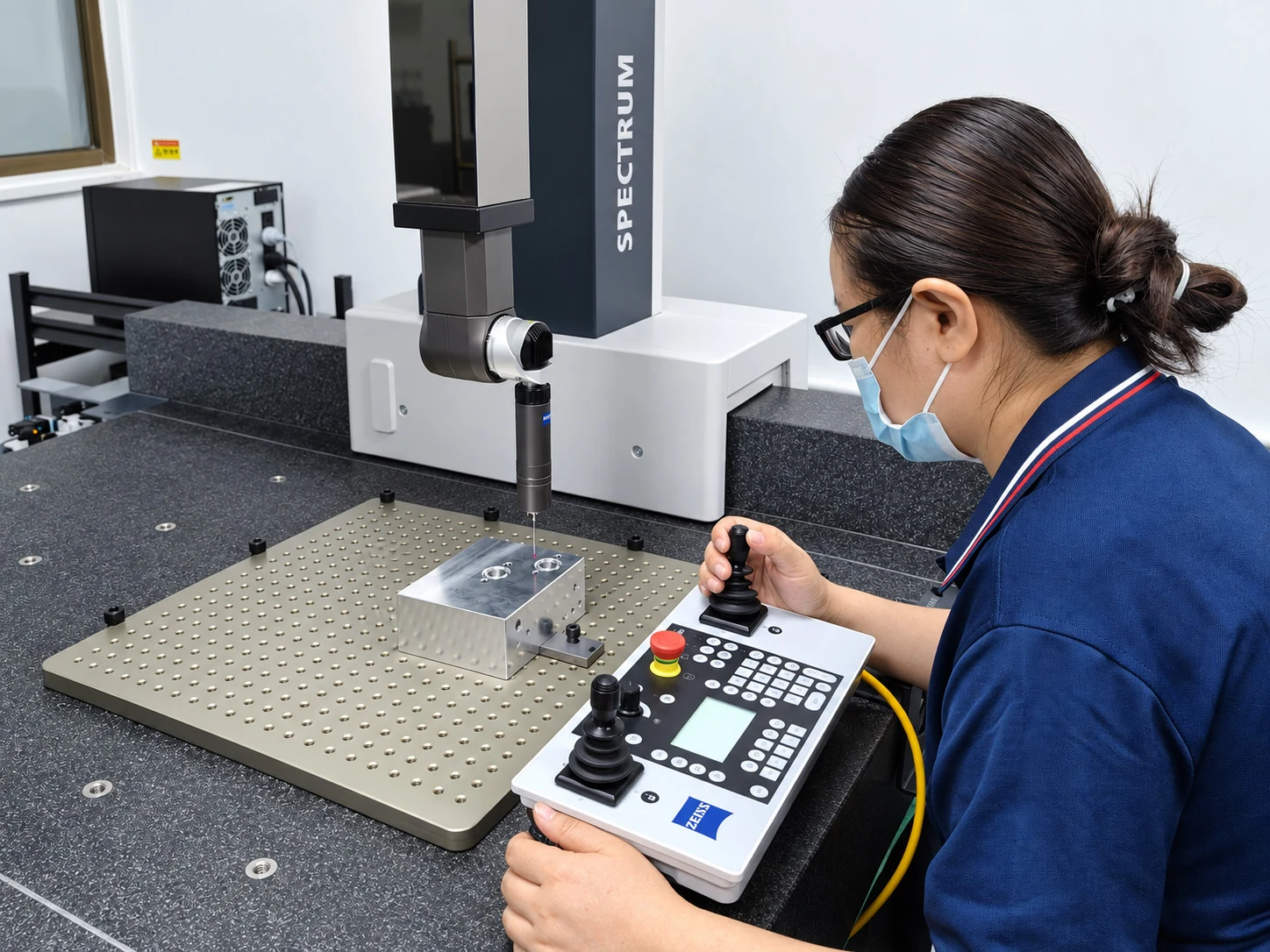
Measurement methods answer different questions
Dimensional measurement and CMM inspection support applicable size and geometry checks. Thread gauges address the specified gauging requirement. Sealing-surface texture needs an appropriate roughness measurement. The method must suit the characteristic, feature access and required evaluation.
A report needs traceable context
Look for part and drawing revision, sample or batch identity, feature identification, nominal requirement and limits, measured result, units and inspection stage. For geometrical requirements, the datum alignment and evaluation must agree with the drawing.
A probe or gauge may not reach every deep internal region. Agree how the relevant characteristics will be assessed, and resolve any verification limitation before manufacturing. A visible bore entrance or an accessible coordinate does not automatically verify the complete hidden feature.
Material certificates and dimensional reports can be provided; first-article and CMM reporting scope are agreed by project. Routine acceptance verifies material and drawing conformity, including applicable dimensions, thread gauging, required bore geometry, sealing-surface roughness and burr removal. Pressure and functional testing are not routine checks for the machined block.
Reference: ZEISS metrology systems. Coordinate measurement and surface measurement have distinct equipment and application requirements. This background does not imply Zhongwei owns every instrument listed.
Inspection resources and method selection Report scope and traceabilityThree ambiguities to resolve before they become a rejection
These are illustrative drawing-review situations, not customer case histories or guaranteed outcomes.
The thread passes, but the sealing step is not documented
Retain the thread result for the requirement it covers. Identify the sealing diameter, depth and surface requirement separately, then agree the needed checks. Do not use successful thread gauging to close the entire cavity inspection.
The drawing and model show different passage depths
Identify the released revisions and the intended intersection. Ask the design owner to resolve the discrepancy, update the manufacturing baseline and confirm the affected feature checks before cutting the passage.
A report is accepted, then the finish changes
Review the changed process against the final bore, thread, masking and surface requirements. Determine which existing results remain relevant and which checks are needed after the changed route.
Questions about manifold drawing requirements
What tolerance can Zhongwei hold on a manifold?
Capability is reviewed for the actual material, feature size, geometry, datum scheme, process route and measurement access. Share the drawing requirement. One advertised plus/minus value would not describe every cavity, deep passage, thread and sealing surface.
Does a bore within its diameter limit also meet roundness and alignment requirements?
A size result alone is not evidence that every required geometrical characteristic has been verified. Interpret the complete drawing under its governing standard and inspect the specified form, location or alignment characteristics with a suitable method.
Can a thread gauge replace valve-cavity inspection?
No. It addresses the specified thread-gauging requirement. Step depths, sealing diameters, geometry, surface texture and passage relationships remain separate features to verify as required by the drawing.
Should I tighten all tolerances to make the manifold more reliable?
Set limits from the functional design and applicable interface references. Unnecessarily tight limits can add machining and inspection work without resolving the actual interface risk. Zhongwei can review manufacturing implications; the design owner approves any tolerance change.
Can you manufacture from a STEP model alone?
A model can support geometry review, but the released definition must also establish material, critical tolerances, datums, surface requirements, cavity references and revision control. Supply the accompanying drawing or complete agreed product definition.
Can ISO and ASME drawing rules be treated as interchangeable?
Use the standard and edition specified for the project. Resolve differences or mixed references with the design owner; do not silently change the interpretation of a requirement.
Does a CMM report prove sealing performance or surface roughness?
A report establishes only the characteristics measured with its stated methods and scope. Dimensional CMM results do not by themselves establish roughness, pressure integrity, functional performance or component cleanliness.
How should inaccessible internal features be accepted?
Identify the relevant feature, requirement and access limitation during review. Agree a suitable verification method and evidence before production, and clarify any unresolved requirement. Do not infer the complete internal geometry from an accessible opening alone.
Send the drawing with the critical features identified
Include the current drawing and matching model, material and condition, governing standard and edition, valve-cavity references, datum features, critical tolerances and surface requirements. Identify the delivery condition, sample and repeat quantities, required reports and any feature that previously caused an assembly or acceptance issue.
DWG, DXF, PDF and JPG drawings and STEP, X_T, IGS or SLDPRT models can be sent by email or WhatsApp. A schematic can start the discussion; manufacturing needs a released definition of the component and its acceptance requirements.
Prepare the complete enquiry