

Start with the equipment constraint that matters to your project
The same application label can cover very different manifold requirements. Use these contexts to identify the interfaces, manufacturing concerns and project information worth reviewing. Suitability and any industry-specific qualification are assessed for the actual component.
Construction and mobile equipment
When the installation envelope is tight, valve access, port orientation and internal passage layout need to work together. Share the approved circuit, mounting envelope and relevant load or vibration requirements so the manufacturing review can focus on the affected features.
Screw-in cartridge valve manifoldsAgricultural equipment
Where several functions are integrated in one block, keep each valve reference and connection traceable to the circuit. Define outdoor exposure, storage conditions and service access alongside the released drawing, especially when similar equipment variants use different interfaces.
Valve and interface reviewRefuse and environmental equipment
Where repeated movement, exposed mounting or washdown is part of the brief, identify the duty cycle, external conditions and maintenance space. Carry those requirements into the approved material, finish, sealing features and component access.
Surface treatment managementIndustrial equipment and power units
Blocks can combine cartridge cavities, face-mounted valves and external connections. Define the exact interfaces, mounting-face requirements and connected passages so a correctly machined feature also belongs to the correct layout.
Power unit manifolds and valve platesMarine, offshore and chemical environments
Separate the internal hydraulic fluid from external salt, moisture, immersion or chemical exposure. Specify the actual conditions and any required approvals before agreeing material, finish and documentation.
Stainless steel manifold requirementsMining, oilfield and other heavy-duty equipment
Provide the engineer-defined pressure and temperature conditions, cycling requirements, installation constraints and qualification documents. An industry name alone does not establish a material, pressure rating or approval route.
Material selection considerationsCompact equipment can require much more than six-face machining
A smaller manifold envelope may place many deep passages close together. The approved layout can include orthogonal intersections, oblique passages and compound-angle holes. The manufacturing challenge is to control their actual position, direction, depth and specified surface condition while keeping intersections accessible for burr removal and inspection.
Preserve the approved connections
Connect cavity and port references to the internal passage layout. Review the intended intersections, surrounding geometry and any ambiguous drilling notes before the affected feature is released.
Plan the cutting sequence
Consider datum transfer, tool access, material condition and the order in which holes meet. Process optimisation aims to reduce burr formation; subsequent deburring, cleaning and checks remain necessary.
Define how the feature will be accepted
Identify critical dimensions and surfaces, the stage of measurement and the available inspection access. Agree a suitable approach for difficult-to-reach features before production.
Bring valve functions into the cylinder-end component
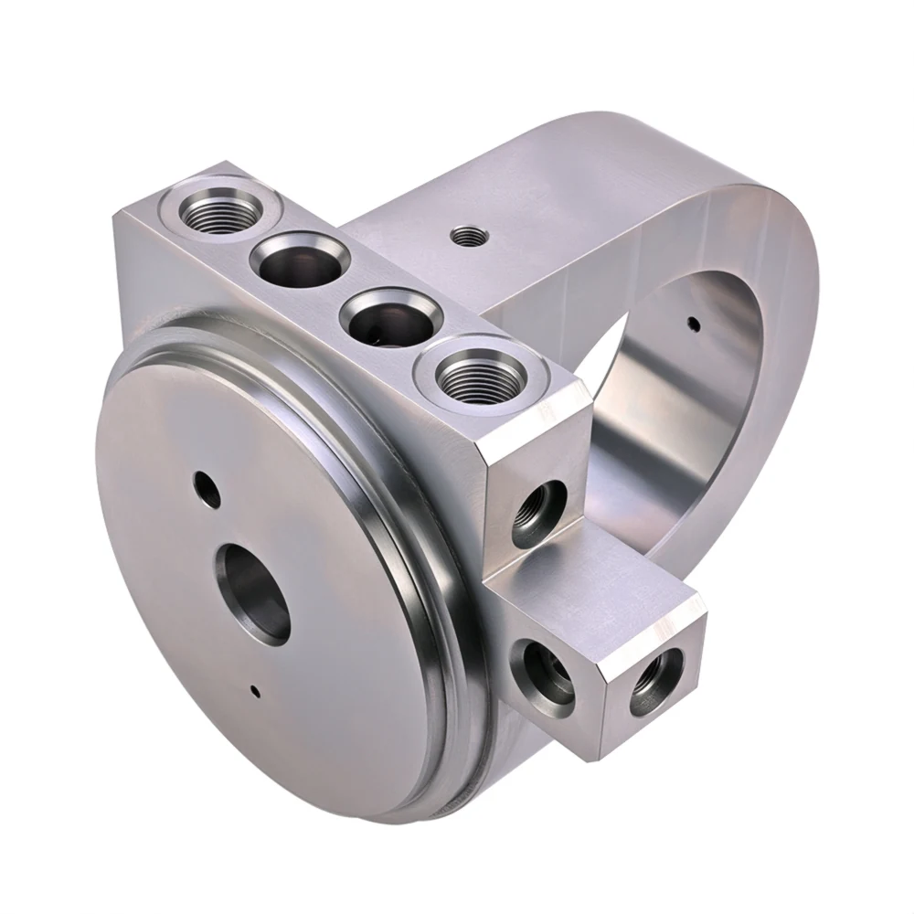
Structural and hydraulic requirements meet in one part
A valve-integrated cylinder end can incorporate counterbalance, load-holding or other functions specified by the customer’s circuit. The component must bring cylinder interfaces, valve cavities, passages and applicable sealing surfaces together in the approved geometry.
For components intended for welding, the actual grade, supply condition, joint and subsequent welding route need to be considered together. Zhongwei’s experience with Q355B and GB 45 includes process control for the specified valve-cavity sealing surfaces; the product page explains the applicable finish requirements and European/US material comparisons.
Q355B and GB 45 cylinder-end valve blocks intended for welding are supplied as machined parts immersed in a no-clean rust-preventive oil and packed in sealed, dust-protective PE bags, without plating, black oxide or phosphating. The specified oil supports welding without a separate oil-removal step, subject to compatibility with the agreed welding procedure.
Explore valve-integrated cylinder endsDefine the exposure before choosing the protection route
An outdoor steel block, a stainless component exposed to a specified chemical environment and a part awaiting welding need different manufacturing briefs. State what contacts the component, at what temperature and for how long, including transport and storage before assembly.
Material and supply condition
Specify the approved grade and condition, including heat treatment or hardness where required. Aluminium, ductile iron, steel and stainless routes involve different trade-offs. The responsible engineer confirms suitability using structure, cycling, temperature and environment as well as pressure.
External protection and internal condition
Define the surfaces that require protection and the final dimensions that must remain within specification. Internal passage coverage, sealing faces and threads need specific attention when planning the chosen treatment.
Project-specific approvals
Identify required material records, inspection documents and any customer or industry approvals at enquiry. A stainless grade or an industry application label does not automatically establish corrosion life or equipment certification.
Steel manifold finish options include black oxide (blackening), phosphating, electroless nickel, zinc and zinc-nickel, as specified for the application. Define the required surfaces, final dimensions and protection conditions; none is the default for every steel block.
Compare material routes Compare surface treatment optionsAsk for evidence that answers the manufacturing question
| Project requirement | Manufacturing focus | Relevant evidence |
|---|---|---|
| The selected valve must fit its cavity | Use the exact valve model and controlled cavity drawing; plan the applicable tooling and finishing operations. | Check the specified threads, bore sizes, depths, geometric relationships and sealing surfaces. |
| The internal connections must follow the drawing | Review drilling directions, depths and intersections; plan machining, deburring and cleaning for the actual layout. | Verify the specified accessible features and agree the method for features with restricted inspection access. |
| The valve or fitting must mount on the intended interface | Control port location, mounting patterns, usable thread depth and the specified face condition. | Use appropriate gauges and dimensional checks; verify applicable roughness separately. |
| The part must use the approved material and condition | Keep grade, condition and any approved substitution tied to the order and drawing revision. | Provide material documentation and any additional agreed checks; comparable grade names alone are insufficient. |
| The approved part must be repeatable | Carry the released drawing, process decisions and critical checks from sample review into repeat orders. | Connect the batch and inspection records to the part revision; review changes before affected production. |
Normal acceptance of our machined manifolds focuses on correct material and conformity to the approved drawing, including the required dimensions, threads, bore geometry, sealing-surface roughness and burr removal. Material certificates and dimensional reports can be provided; first-article and CMM reports are agreed by project.
Pressure and functional testing are not routine checks for these machined blocks. The responsible engineering team approves the circuit, structural suitability and system validation. Dimensional inspection demonstrates the measured component features; it does not independently establish equipment performance.
Inspect the specified features Connect records to the delivered partMake the first sample useful for the next production run
Agree the manufacturing basis
Bring together the current drawing and model, valve and interface references, material, finish, quantities and acceptance requirements. A schematic can start a discussion; identify who prepares and approves the remaining part definition.
Resolve sample findings
Compare measured results with the approved requirements and record the customer’s assembly feedback. Separate a drawing change from a manufacturing correction so the next batch has a clear release basis.
Carry decisions into repeat supply
Retain approved revisions, critical checks and agreed delivery conditions. Review changes to material, cavities, interfaces or treatment before they affect ongoing production.
Questions about your equipment application
Can I enquire if my equipment type is not listed here?
Yes. Send the manifold requirements, equipment context and available drawings. We review the actual geometry, material, manufacturing scope and acceptance needs rather than deciding from the industry name alone.
Can you start from a schematic without a complete manifold drawing?
Yes, a schematic and valve list can start the discussion. We identify missing interface and manufacturing information, then agree the scope and responsibility for the approved part definition before machining.
Do you supply complete hydraulic systems or machined manifold components?
This website focuses on custom machined manifolds and related cylinder-end valve blocks. Define any requested valves, assembly or additional work separately so the quotation states the agreed supply scope.
Does an application or material name establish a pressure rating?
No. The responsible engineer evaluates the actual material condition, geometry, wall sections, operating conditions and project requirements. A grade name or connection standard alone is not a rating for the complete manifold.
Can stainless steel automatically qualify a manifold for offshore or chemical service?
No. Specify the fluid and external exposure, temperature, material condition and any required qualification. Suitability and approval follow the actual project requirements.
What evidence can support a sample review?
Material documentation and dimensional results can support acceptance of the machined part. Agree the critical features, inspection methods and any first-article or CMM reporting before production. System-level validation remains separate.
Tell us what the manifold needs to fit, connect and withstand
Send the equipment context, approved drawing and model, valve references and the requirement that matters most: limited space, a difficult sealing surface, complex passages, welding, exposure or repeat-order consistency. Include quantities, requested timing and inspection records, and identify any qualification needed.
Complete manifold drawings are preferred. We also accept schematics for initial discussion, 2D DWG, DXF, PDF and JPG files, and STEP, X_T, IGS and SLDPRT models by email or WhatsApp. Contact us before sharing confidential files if an NDA is needed.
Prepare your manifold enquiry