
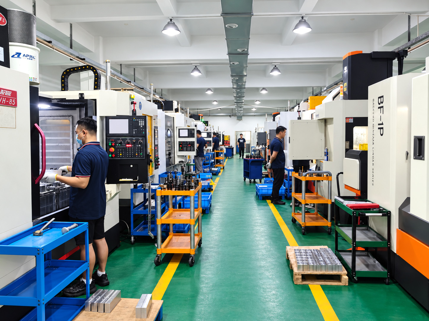
The challenge is how the features meet inside the block
Compact manifolds can contain many deep passages, orthogonal and oblique intersections, and holes drilled at compound angles. Machining six external faces is only part of the work. The process must bring the internal connections to the specified positions and depths while preserving the required bore geometry and surface condition.
An intersection also changes how a tool enters or breaks through a surface and where burrs can form. We consider the drilling direction, setup, tooling and order of operations together, including access for later deburring, cleaning and inspection. Reducing burr formation during machining supports the subsequent cleaning work; it does not replace it.
Explore complex multi-sided machiningFind the process behind your main manufacturing concern
Valve-cavity tooling
A correct thread alone does not establish a correct cavity. We work from the specified valve model and cavity drawing, with attention to stepped diameters, depths and sealing areas. Dedicated and non-standard tooling support the approved geometry.
Valve cavities and toolingMulti-sided and angled features
Features on different faces must relate to the same drawing datums. Setup and process planning address cross-face locations, oblique holes and compound-angle passages according to the actual part.
Multi-sided machiningDeep and intersecting passages
Drilling direction, tool access, chip evacuation and intersection geometry influence the manufacturing route. We review these details alongside the ability to clean and check the relevant features.
Deep-hole and cross-hole machiningDeburring and cleaning
Intersections and cavities need specific attention after cutting. The route connects burr removal, cleaning, accessible checks and protected handling to the geometry and agreed delivery requirements.
Internal deburring and cleaningSurface treatment management
Treatment can affect the finished dimensions and surfaces that matter to assembly. Agree the specified treatment, protected areas and final inspection condition, with the treatment provider where applicable.
Surface treatment managementSample to repeat production
Sample findings and approved changes need to carry into subsequent orders. Connect the released revision to tooling, setups, inspection requirements and production planning.
Production control and lead timePlan the route around the finished requirement
01 · Define the manufacturing basis
Confirm drawing and model revisions, material and condition, cavity references, critical features and the required delivery state. Resolve conflicting or missing details before they become machining instructions.
02 · Connect the operations
Plan datums, setups, drilling directions, tool access and finishing steps together. Consider what the next operation will do to an already-machined feature and when a difficult intersection can be cleaned or checked.
03 · Review the finished part
Verify the material and specified features in the agreed final condition. Connect inspection findings and sample decisions to the documents used for repeat production.
Manufacturing suggestions are reviewed with the customer’s responsible engineer. A proposed change to a passage, access hole, interface or material is not a substitute for approval of the part definition.
Review manufacturability before productionThe material and next operation shape the delivery condition
Aluminum, ductile iron, carbon and alloy steels, and stainless steels create different machining and finishing requirements. The specified grade, heat-treatment or delivery condition, geometry and surface requirements determine the process review. Material selection for the operating conditions remains with the responsible design engineer.
Specified surface treatment
Where required, steel finishing options include electroless nickel, zinc, zinc-nickel, black oxide and phosphating. Aluminum anodizing is another project-specific route. These processes serve different requirements and are not interchangeable defaults.
Manage treatment and final dimensionsCylinder ends intended for welding
For the Q355B and GB 45 steel cylinder-end blocks in our agreed welding route, delivery uses no-clean rust-preventive oil and sealed dust-protective PE bags. Plating, black oxide and phosphating are not the default. The oil and subsequent welding process must be compatible with the agreed route.
Valve-integrated cylinder-end blocksThe material-specific pages explain grade choices and Chinese, European and US comparison references. A comparison candidate does not authorize substitution for the material specified on the order.
Compare manifold materials and delivery conditionsSee the resources, then connect them to your part
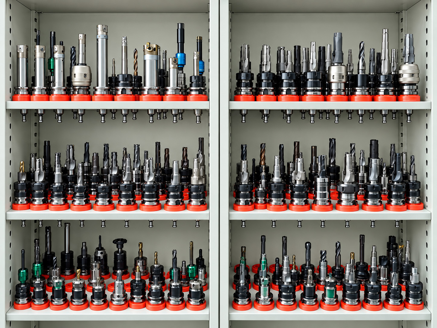
Tooling experience
Our tooling resources support discussions about cavity machining and non-standard features. Confirm the reference drawing and the actual geometry for your project; a tool photograph does not establish universal valve compatibility.
See the workshop and equipment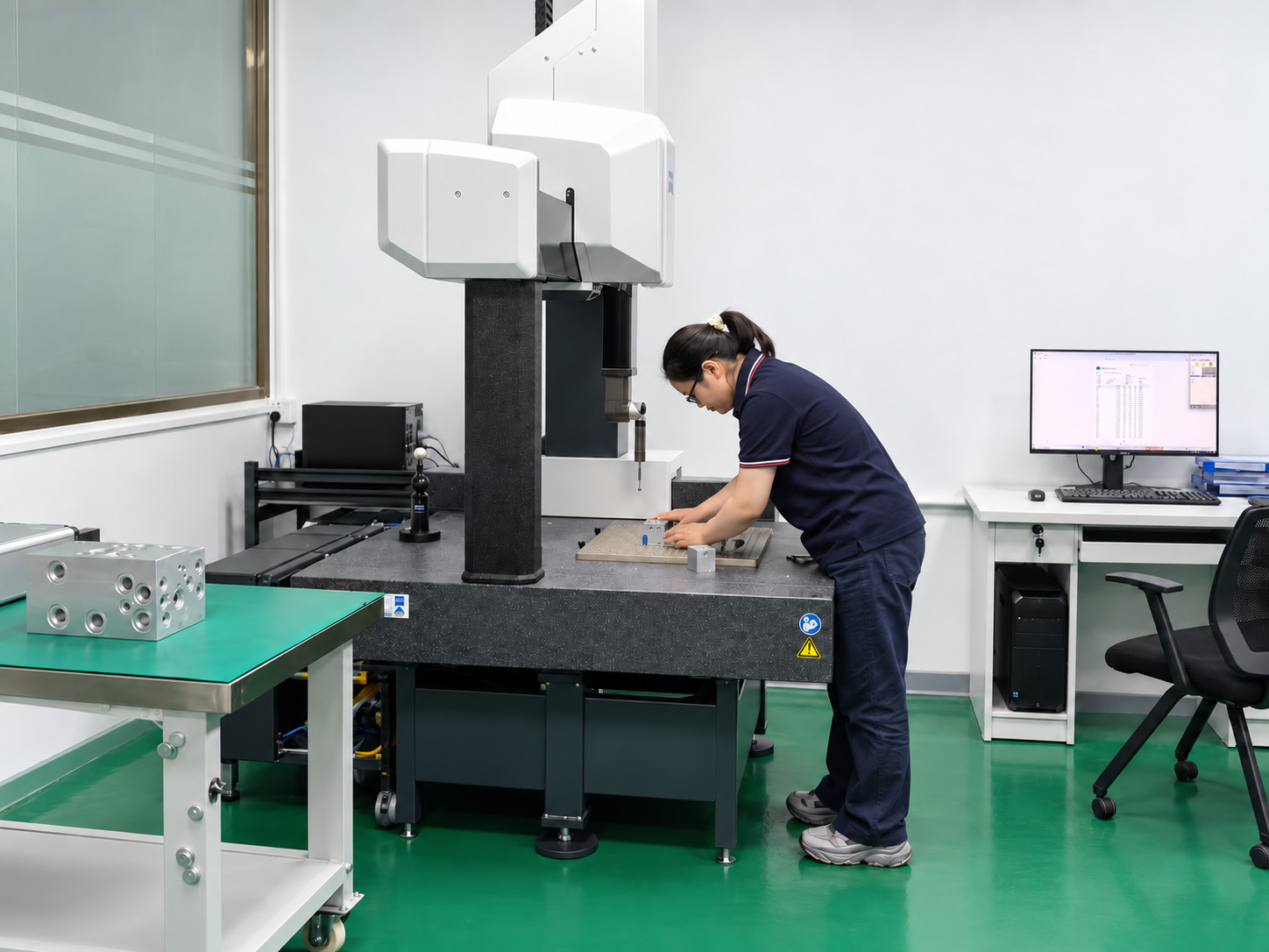
Drawing-based checks
Inspection addresses specified dimensions, applicable bore geometry, thread-gauge acceptance, sealing-surface roughness and burr removal. Material certificates and dimensional reports support the agreed scope.
See inspection methods and reportsOur normal machined-block acceptance checks material and drawing conformity. Pressure and functional testing are not routine checks. Formal component cleanliness verification is separately agreed when required; manufacturing cleaning by itself is not a third-party test report.
Connect manufacturing to the acceptance planQuestions about your manufacturing route
What does build-to-print manifold manufacturing include?
We manufacture the component against the customer-approved drawing and agreed technical requirements. The review connects material, valve-cavity references, tolerances, finish and inspection to a practical machining route. Missing details and proposed changes require agreement before production; the responsible design engineer retains approval of the design and material selection.
Can you review a manifold with angled or compound-angle holes?
Yes. Share the complete geometry and the relevant position, depth and surface requirements. We assess the setups, access, intersections, cleaning and inspection needs for the actual part; capability is confirmed by project.
Can machining prevent every internal burr?
Process planning can reduce burr formation, including through tooling and the sequence of intersecting operations. Burr removal, cleaning and suitable checks are still needed. We do not promise that machining alone leaves every internal feature burr-free.
What determines the production lead time?
Material and condition, cavity-tool preparation, part complexity, quantity, external treatment, inspection and sample approval all affect the plan. Timing is confirmed for the project and current production schedule.
What if we have only a schematic or a sample?
Either can start a discussion. We identify what remains to be defined, including valve references, interfaces, material and acceptance criteria. Manufacturing proceeds against an approved part definition, with the scope and engineering responsibilities agreed.
Show us the feature that needs particular attention
Send the drawing and model revisions, material and condition, quantities, cavity references and critical requirements. Highlight difficult intersections, sealing surfaces, treatment restrictions or previous machining problems so the discussion starts with the right details.
Complete manifold drawings are preferred. We accept DWG, DXF, PDF and JPG drawings, and STEP, X_T, IGS and SLDPRT models by email or WhatsApp. A schematic can start the discussion when the part definition is still being developed.
Prepare your manufacturing enquiry