
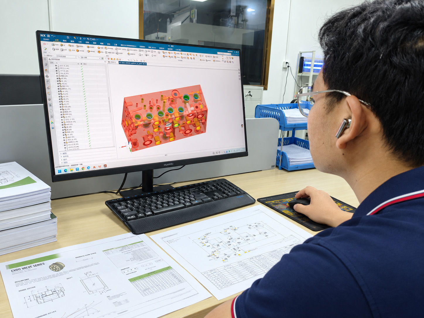
A circuit diagram and a manifold drawing answer different questions
A hydraulic schematic describes components and their intended connections. A manifold drawing defines the physical block that implements the agreed arrangement. Keeping these roles clear helps prevent a missing valve reference, connection or port detail from becoming an assumption during manufacture.
What to take from the schematic
Identify the relevant components, connections, control paths, labels and specified settings. Use the drawing legend and referenced documents to understand what the designer has actually defined.
What still needs a part definition
Material and condition, block dimensions, cavity geometry, port form, drilling position and depth, tolerances, surface requirements and delivery condition belong in the released manufacturing information.
What a photograph can show
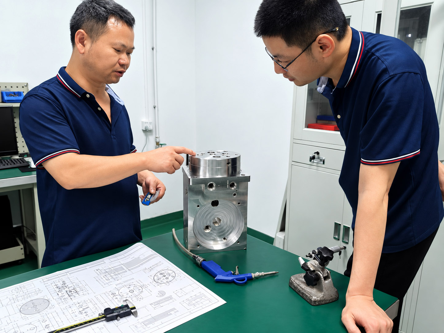
The Zhongwei manifold photograph above illustrates a physical component. Its visible holes do not disclose the complete internal circuit or establish the function of a particular valve arrangement.
The position of a symbol on a page is not a machining coordinate. A line joining symbols does not tell the machinist which face to drill, what diameter to use or where two passages should intersect.
Reference framework: ISO 1219-1: graphical symbols and ISO 1219-2: circuit diagrams. Use the convention and edition specified for the project, together with the drawing legend and component documentation.
Read the drawing in an order that produces useful project information
| Reading step | What to look for | What to record |
|---|---|---|
| 1 · Establish the document baseline | Read the title, revision, units, notes, legend and referenced documents before tracing a circuit. | Identify the approved version and any missing pages, unclear symbols or superseded references. |
| 2 · Mark the manifold boundary | Identify which components and connections belong in the block, which mount on it and which remain elsewhere in the system. | A marked integration boundary and a list of external connections prevent an external function from being assumed to be inside the block. |
| 3 · Match each component identifier | Follow each relevant tag to the valve list and the exact model or ordering reference. | Record the data sheet and cavity or mounting reference; flag undecided selections rather than selecting a cavity from the symbol alone. |
| 4 · Trace each required connection | Follow the line from its labelled endpoint to the other endpoint, including continuations to another sheet. Read junctions and crossings under the drawing convention. | List the connected identifiers and ports. If a junction or line meaning is unclear, ask the designer to resolve it. |
| 5 · Trace control and auxiliary paths | Read pilot, drain, sensing and other auxiliary connections using the legend and the selected component documentation. | Keep them identifiable in the connection record. Do not merge a drain with a return path or omit a small line merely because it carries less flow. |
| 6 · List the missing manufacturing inputs | Compare the schematic with the model, part drawing and interface references that are available. | Create a short list of open items, the document affected and the person responsible for the decision. |
Keep connections and assumptions separate in your notes. A confirmed connection can move into the approved layout; an unclear connection needs a recorded answer before the affected passage is released for machining.
Make a connection record without inventing the physical layout
A simple connection record is useful when a drawing contains many valves or spans several sheets. Give each entry two identifiable endpoints and a source reference. The following examples describe how to record information; they are not a hydraulic circuit or a customer case.
| Connection being recorded | Information to carry forward | Information not established by that entry |
|---|---|---|
| External supply connection to a specified valve port | Record the exact external label and the valve identifier and port designation shown in the schematic and valve documentation. | The label alone does not define an external thread, sealing method, port face or passage size. |
| One valve port to another component port | Record both component identifiers, both port designations and the relevant sheet or continuation reference. | Cavity positions, drilling directions, intersections and remaining walls need the approved manifold layout. |
| Pilot, drain or sensing connection | Record its exact purpose and endpoints as confirmed by the designer and component documents. | Do not assume that it shares another passage or terminates internally when the documents leave that undecided. |
| Connection leaving the manifold boundary | Identify the external device or circuit reference and the required block-side label. | The mating connection, installation access and responsibility for external piping still need definition. |
Labels such as P, T, A and B are useful only in the context of the drawing and selected component. Preserve the designer’s labels, confirm their meaning and map them consistently to the valve documents and manifold drawing. A label or number on one valve should not be assumed to mean the same physical port on another valve.
Translate confirmed connections into passage-layout reviewRead the intended state as well as the connection
A valve symbol may show alternative switching positions, an actuation method, a spring or a pilot control. Those details matter when tracing the intended path. The project still needs the designer’s description of the operating states that are relevant to the manifold.
Identify the state being discussed
State whether the drawing discussion concerns rest, an actuated condition or another defined operating state. Follow the connections for that state; do not treat every path shown inside a multi-position symbol as open at the same time.
Keep settings tied to selected components
Where pressure, flow or other settings are specified, connect the note to its component identifier and supporting data sheet. If the setting is not defined, keep it open for the responsible engineer rather than assigning a value during manufacturing preparation.
Ask about unclear transitions
Where sequence, load holding or another state-dependent function is important, request the designer’s intended behaviour and references. A static drawing review does not independently verify transient behaviour or the completed system’s performance.
This guide supports communication of circuit information for manufacturing. Circuit design approval, valve suitability and system safety remain with the responsible engineering team.
Discuss the scope of a schematic reviewConnect the schematic to the documents that define machining
Valve list → physical interface
Use the exact valve model and current cavity or mounting drawing. Similar circuit symbols, threads or product names do not establish interchangeable cavities. Match each identifier to the correct machining reference.
Connection record → passage geometry
The approved layout defines where passages run and how they intersect. Compact blocks may use deep, oblique or compound-angle passages. Manufacturing review considers access, direction, depth, walls, burr formation, cleaning and the checks available for the actual geometry.
Part definition → acceptance
The released drawing and referenced specifications establish material, dimensions, datums, threads, sealing surfaces, roughness and delivery condition. Inspection verifies those requirements at the agreed stage.
A clearer schematic reduces ambiguity, but it does not automatically complete the manifold design. Agree who prepares and approves the remaining model and drawing, and what design or review work is included in the project scope.
Zhongwei’s normal machined-block acceptance focuses on material and drawing conformity. Pressure and functional testing are not routine checks. Material certificates and dimensional reports can be provided, with first-article and CMM reporting agreed by project.
Confirm the valve and port interfaces Review the manufacturing definition Understand drawing-based inspectionClose the gaps that commonly delay a useful quotation
A symbol is present, but no valve is selected
List the selection as open. The cavity or mounting interface, installation space and manufacturing route may depend on the approved model. A functional description alone should not become a guessed machining reference.
The circuit and block use different port labels
Prepare a cross-reference and ask the design owner to confirm it. If the connection itself differs, resolve the affected documents rather than renaming a port to conceal the disagreement.
A diagram is legible, but project context is missing
Add the intended application, designer-defined operating conditions, installation envelope, material or finish requirements, quantity and supply scope. Identify what remains undecided so an initial discussion can be separated from a firm manufacturing quotation.
When issuing a revision, identify the changed component or connection and replace the affected documents together. Keep the released set distinct from proposals, marked-up discussion copies and previous versions.
Keep documents and revisions connectedQuestions about preparing a schematic for a manifold enquiry
Can I start a manifold enquiry with only a hydraulic schematic?
Yes. Send the current schematic and the valve references and project context you already have. Missing information can be identified during discussion. The component still needs an approved manufacturing definition before machining.
Does the position of a symbol tell you where to machine its cavity?
No. Symbol placement communicates the diagram’s circuit arrangement. Cavity position, orientation, access and passage geometry must be established by the manifold layout and approved part drawing.
How should an unclear line crossing be handled?
Check the drawing convention, legend, junction notation and any continuation reference. If the connection remains ambiguous, mark it for clarification by the designer instead of guessing whether the lines connect.
Does a hydraulic symbol identify the exact valve model?
Not by itself. Match the component tag to the valve list, complete ordering reference and supporting documents. Use the applicable cavity or mounting drawing to define the physical interface.
Can pilot and drain connections be left out of the enquiry?
Include all connections relevant to the proposed manifold and identify their endpoints. Their routing requirements come from the circuit designer and the selected component documentation; they should not be assumed or merged for convenience.
Is a marked-up PDF acceptable for the first discussion?
Yes, if the symbols, labels and notes are legible. Mark the revision and open questions clearly. Keep informal annotations separate from the released manufacturing requirements until they are confirmed.
Does a schematic review approve the system function?
No. It helps clarify information for the manifold project. Circuit approval and system validation remain separate responsibilities; dimensional inspection of the block does not prove complete-system performance.
What should accompany a STEP model and schematic?
Include the matching part drawing, valve list, interface references, material and condition, critical dimensions and roughness, delivery requirements and requested inspection records. Resolve revision conflicts before releasing work.
Send the circuit with its confirmed references and open questions
Provide the legible schematic and revision, valve list, known cavity or mounting references, external connection labels and manifold boundary. Add the intended operating and installation context, quantities and supply requirements. Highlight any selection or connection that still needs an engineering decision.
Send DWG, DXF, PDF or JPG drawings by email or WhatsApp. If available, include STEP, X_T, IGS or SLDPRT models and their matching drawing revision. Complete manifold drawings are preferred; a schematic can begin the discussion. Contact us before sharing confidential files if an NDA is needed.
Complete manifold enquiry checklist