
A matching thread does not establish a compatible valve cavity
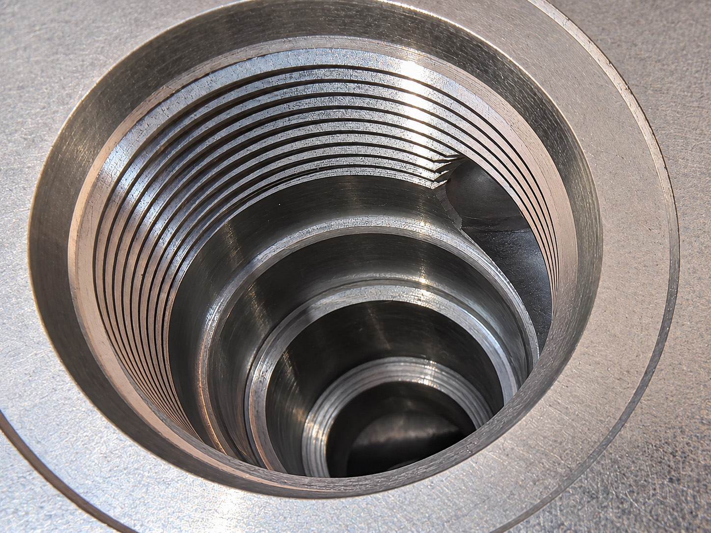
A screw-in cartridge valve cavity is a set of related features: threads, stepped bores, locating surfaces, sealing areas and connections to internal passages. A valve may begin to screw into a block while another feature remains wrong. Finding that difference after finishing can turn a small reference error into a rejected component.
Thread match
Nominal diameter and pitch identify only part of the interface. Thread form, tolerance class and required engagement also need definition; none of these establish the complete bore geometry.
Cavity match
The approved cavity reference defines the applicable steps, depths, sealing diameters and other requirements. Compare the complete drawing and notes, including the relationship to cross-drilled passages.
Application match
Even when two valves use the same cavity, their function, port logic, settings, seals and operating limits still need engineering approval. Mechanical fit alone does not approve a valve substitution.
For an existing block, preserve the original cavity designation and revision while reviewing a proposed change. Record the differences before changing the valve, drawing or machining program.
Name the interface before choosing its standard
| Reference type | What it describes | What to confirm |
|---|---|---|
| Manufacturer cavity drawing | The cavity designation specified for the exact valve model, with the applicable drawing revision. | Use the complete geometry and notes. A brand name, nominal size or family name alone is insufficient. |
| ISO 7789 screw-in cartridge cavities | A standard covering cavities for two-, three- and four-port screw-in cartridge valves. | Identify the specific cavity designation and applicable edition. Do not assume every manufacturer cavity follows this standard. |
| Valve mounting surface | An interface on a face of the block; ISO 4401 addresses mounting surfaces for four-port directional control valves. | A mounting pattern does not specify a screw-in cartridge cavity. Confirm the selected valve’s mounting drawing and additional requirements. |
| External connection port | The fitting connection and its specified thread and sealing arrangement. | An external oil port is a different interface from a cartridge cavity, even when thread descriptions look similar. |
ISO 7789:2007 and ISO 4401:2005 address different interfaces. Use the project-specified edition and the selected component’s documentation. If the references conflict, obtain a recorded decision from the design owner before manufacturing the affected feature.
Read the port and mounting-interface guideRead the features that a cavity name cannot tell you
Use this checklist alongside the controlled cavity drawing. It explains what to look for; it does not replace the dimensions, tolerances or inspection instructions for a particular valve.
| Drawing feature | What to read | Why it matters |
|---|---|---|
| Cavity identity, units and notes | Check the designation, revision, dimensional units and all general and feature-specific notes. | A recognisable outline or converted model can omit a tolerance, surface requirement or revision change. |
| Depth reference and locating surfaces | Identify the face or shoulder from which each depth is measured, together with the specified seating or locating geometry. | Measuring from the wrong face can shift several steps even when their individual sizes appear correct. |
| Thread definition | Read thread form, size, pitch, class, usable length and any related entry or relief details. | A matching nominal thread does not establish engagement or prove the remaining cavity geometry. |
| Bore steps and geometric relationships | Read each diameter and depth, plus any specified alignment, roundness or other geometric control. | A thread check cannot detect every out-of-position or incorrectly sized sealing bore. |
| Sealing surfaces and entry edges | Identify the actual sealing regions, roughness callouts, chamfers, radii and edge requirements. | Damage, unsuitable roughness or an incorrect entry can affect the seal; do not apply one roughness value to the entire cavity. |
| Passage intersections | Check where the approved manifold passages enter relative to the cavity steps, seals and port designations. | A correct cavity tool does not establish the location of a separately drilled passage or the condition of its intersection. |
| Final manufacturing condition | State which dimensions and surfaces apply after the specified finish, and identify any masking or process allowances to be agreed. | An acceptable pre-treatment result may not represent the delivered cavity. Reconcile coating and dimensional requirements before production. |
For example, two descriptions can quote the same thread while giving different step depths or sealing diameters. Treat that as a difference to resolve, not permission to use the same cavity. This is an illustrative comparison, not a claim about any particular valve pair.
Clarify dimensions, datums and drawing requirementsKeep the valve, cavity and manifold revisions connected
1 · Identify the source
Start with the full valve model and its manufacturer’s cavity reference. Obtain the current reference for review, then record the exact revision approved for the project. A website link alone does not preserve the released manufacturing basis.
2 · Reconcile the drawing set
Match the cavity reference to the manifold drawing and model. If they disagree, list the affected features and obtain an approved resolution. A newer download should trigger a change review rather than silently replace a released requirement.
3 · Record the release
Keep the approved cavity reference, manifold revision and agreed clarifications together. Repeat orders and valve changes can then be checked against the same documented baseline.
A 3D model is useful for layout and tool access, but the available file may not contain tolerances, surface finish or all drawing notes. A sample can support investigation; it cannot by itself establish every original requirement.
Connect drawings to batch documentationTurn each critical requirement into a process decision and a check
At Zhongwei, cavity information feeds the tooling and manufacturing review: the material and condition, feature geometry, finishing sequence and inspection access must work together. Dedicated cavity tools support repeatable geometry, while tool condition, cutting strategy and checks remain part of the process.
Tooling and bore geometry
Check the proposed tool against the approved cavity drawing. Define the bore sizes, depths and geometric relationships that need verification, using methods suitable for the feature and its accessibility.
Threads and sealing areas
Use the specified thread gauges for thread acceptance. Check applicable sealing-surface roughness separately. Passing a thread gauge does not prove step depth, sealing-bore geometry or surface finish.
Intersections and delivery condition
Plan burr removal and cleaning around cross-hole intersections without changing specified sealing edges. Carry the agreed finishing and inspection stage into the records for the delivered part.
Normal machined-block acceptance verifies the specified material and drawing requirements. Material certificates and dimensional reports can be provided; first-article and CMM records are agreed by project. CMM results cover the measured geometry and do not replace roughness checks. Pressure and functional testing are not routine acceptance checks for our machined blocks.
See cavity tooling and machining control See feature-based inspection See deburring, cleaning and packagingQuestions about cartridge valve cavity specifications
Are cartridge valve cavities universal?
No. Use the cavity drawing identified for the selected valve. Standardised and manufacturer-specific references both exist; a nominal size or similar thread does not establish compatibility.
What does ISO 7789 cover?
ISO 7789 addresses cavities for two-, three- and four-port screw-in cartridge valves. Specify the applicable cavity designation and edition. It is not a general approval of every valve, material or manifold design.
Is ISO 4401 a screw-in cartridge cavity standard?
No. It addresses mounting surfaces for four-port directional control valves. A manifold may contain both mounting surfaces and cartridge cavities, each with its own references.
Can a valve with the same cavity replace the original valve?
A common cavity can support mechanical fit, but the design owner still needs to confirm function, port logic, seals, ratings and installation requirements. Cavity compatibility alone is insufficient for substitution approval.
Can I specify only a nominal size or thread?
That is useful preliminary information, but it is incomplete for machining. Add the full valve model, cavity designation and controlled drawing, including the required geometry and notes.
Does a GO/NO-GO thread check prove the cavity is correct?
No. It addresses the thread requirements covered by that gauge. Bore steps, depth references, sealing surfaces, passage intersections and other specified features require their own appropriate checks.
Can an existing sample or STEP file replace the cavity drawing?
It can help start the review, but may not define tolerances, roughness, material requirements or all applicable notes. Resolve missing information and approve the manufacturing definition before machining.
Can Zhongwei machine a non-standard cavity?
We can review a non-standard cavity from a controlled customer or valve-supplier drawing. Tooling, material condition, critical surfaces and inspection access are assessed before confirming the manufacturing approach.
Use original references for the exact interface
The links below help locate the appropriate source. They do not establish compatibility with a specific Zhongwei part or imply manufacturer approval or affiliation. Retain the complete documents approved for your project.
- ISO 7789:2007 — screw-in cartridge valve cavities: standard scope and edition reference.
- ISO 4401:2005 — directional valve mounting surfaces: a separate interface category.
- HydraForce technical reference — 06-size, 2-way cavities: an example of a manufacturer’s cavity reference page; use the drawing specified for your actual valve.
Send a cavity reference that can be traced to your valve
Include the manufacturer and complete valve model, cavity designation and revision, and matching manifold drawing or model. Add material and condition, surface treatment, quantities and critical inspection requirements. Mark any conflict or proposed valve change for review.
DWG, DXF, PDF and JPG drawings are accepted, together with STEP, X_T, IGS or SLDPRT models. Complete manifold drawings are preferred; a schematic and valve list can begin the discussion. Contact us before sharing confidential files if an NDA is needed.
Request a project-specific cavity review