
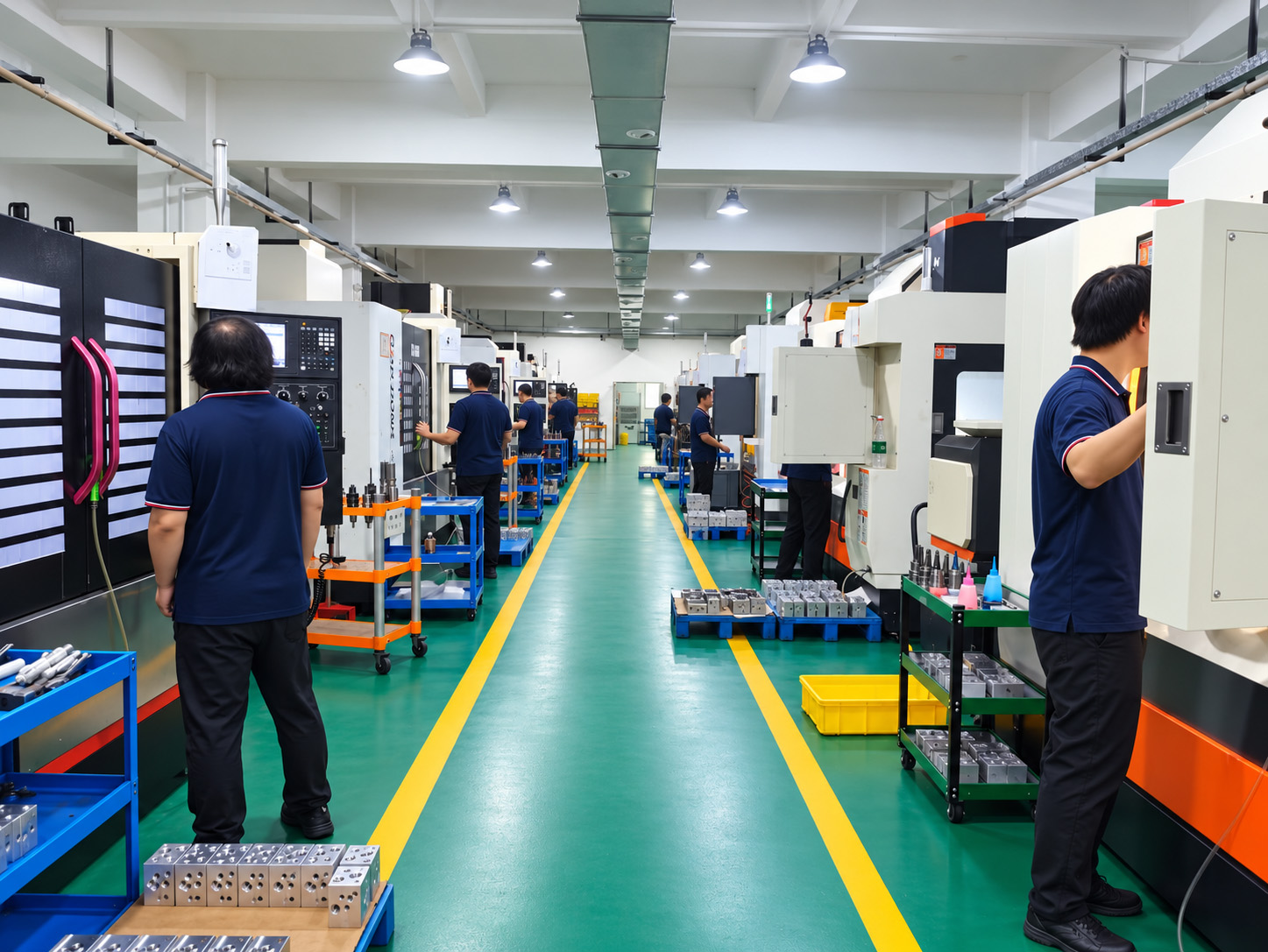
A workshop in Dongguan, focused on the details of your manifold
Zhongwei brings CNC machining, valve-cavity tooling, experienced operators, cleaning and dimensional inspection together for custom hydraulic manifolds and related cylinder-end valve blocks. The manufacturing plan starts with the approved part definition and the features that need particular control.
The part defines the resources
Material condition, cavity geometry, passage layout and inspection access determine the tooling, setup and checks required. We review those details before confirming the manufacturing route.
People connect the operations
Machining experience matters at the handovers: transferring datums between setups, managing tool condition, recognising difficult intersections and checking the surfaces that will seal.
Evidence follows the requirement
Factory photographs show the working environment and activities. Part acceptance comes from the approved drawing, relevant measurements and agreed records for the actual order.
Factory address: Room 103, Building 13, No. 99 Hongye North Road, Tangxia Town, Dongguan, Guangdong, China 523710.
Review the manufacturing requirementsTooling and hands-on work support the process
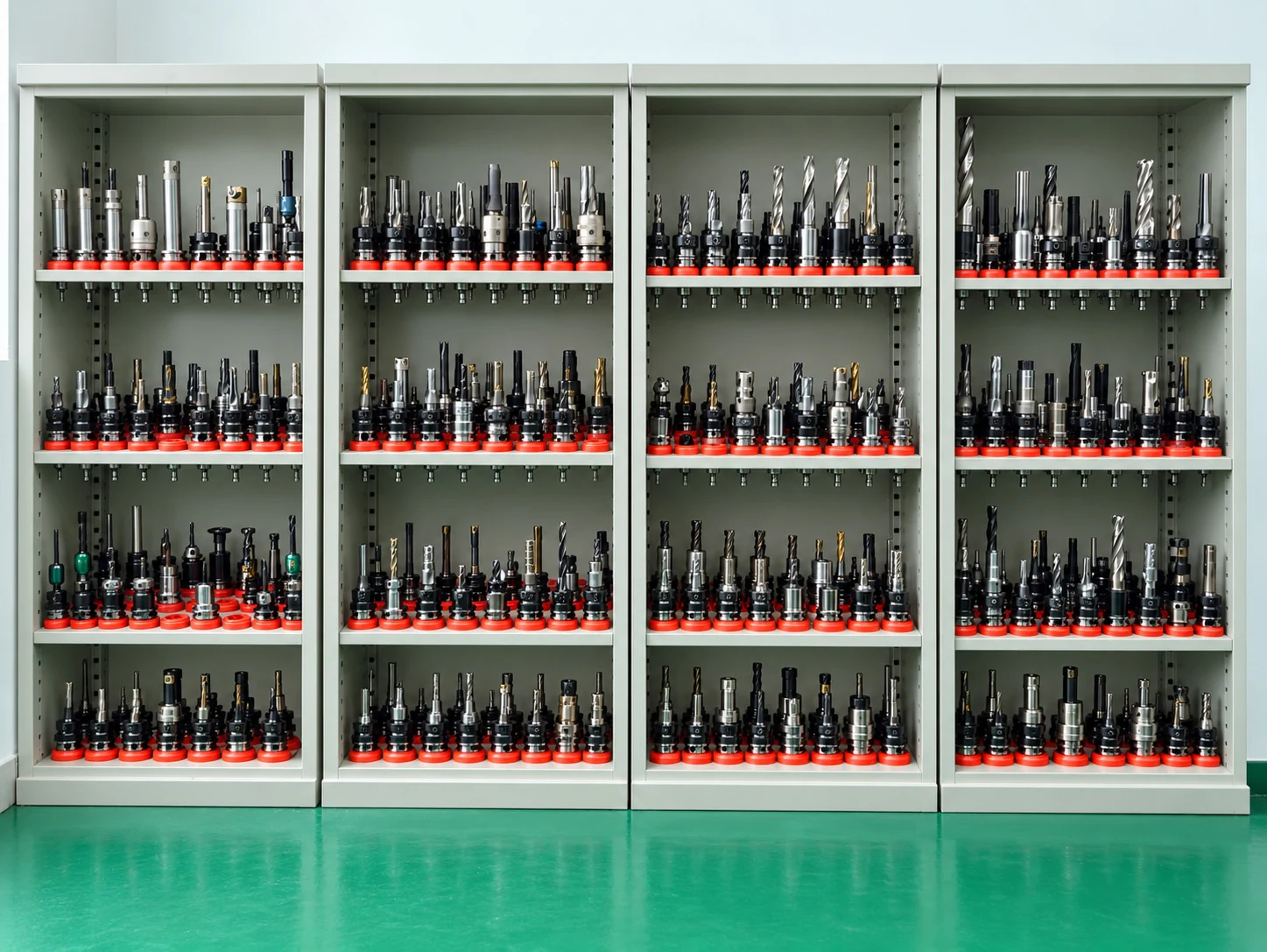
Cavity tooling and preparation
Dedicated cavity tools and non-standard tooling development support the geometry specified by the valve supplier or customer. The tool is checked against the complete cavity reference, including steps, depths and applicable sealing features.
Explore cavity tooling
Burr control and cleaning
Experienced manual work remains important around deep and intersecting passages. Burr removal, cleaning, handling and packaging need to follow the actual geometry and delivery requirements. Air blow-off shown here is one operation within that process.
Explore deburring and cleaningA stocked tool or a cleaning operation does not establish that every cavity or internal feature is ready for delivery. The approved drawing, material and condition, tool suitability and required checks remain connected throughout the manufacturing plan.
The machining challenge is the relationship between the holes
A manifold may have features on several faces, but machining the faces is only part of the task. Dense internal passages can be deep, oblique or at compound angles. Their location, direction and depth must follow the approved layout while the specified bore geometry and sealing-surface condition remain controlled.
Datums, workholding and access
Plan how the part is located through successive operations, which features establish the references and how the tool reaches each hole. Cross-face relationships need to be preserved through the setup sequence.
Material, cutting and finishing
Match the tool and finishing approach to the material condition and critical surfaces. Tool wear, cutting sequence and finishing allowance affect the repeatability of the result; machine presence alone does not establish a finished-part tolerance.
Intersections and burr formation
Review where the cutting tool enters or breaks into another passage. Process optimisation aims to reduce burr formation, followed by the required deburring, cleaning and checks for the actual feature.
For a new project, block size, geometry, material, workholding and inspection access are reviewed together before capability and timing are confirmed. Sample findings and approved changes are carried into the repeat-production basis.
Multi-sided and compound-angle machining Deep-hole and cross-hole control From sample to repeat productionInspection resources are chosen for the specified feature

Coordinate measurement
Our metrology resources include a ZEISS CMM for suitable dimensional and geometric checks. The measurement plan follows the drawing’s datums, critical features and accessible geometry.
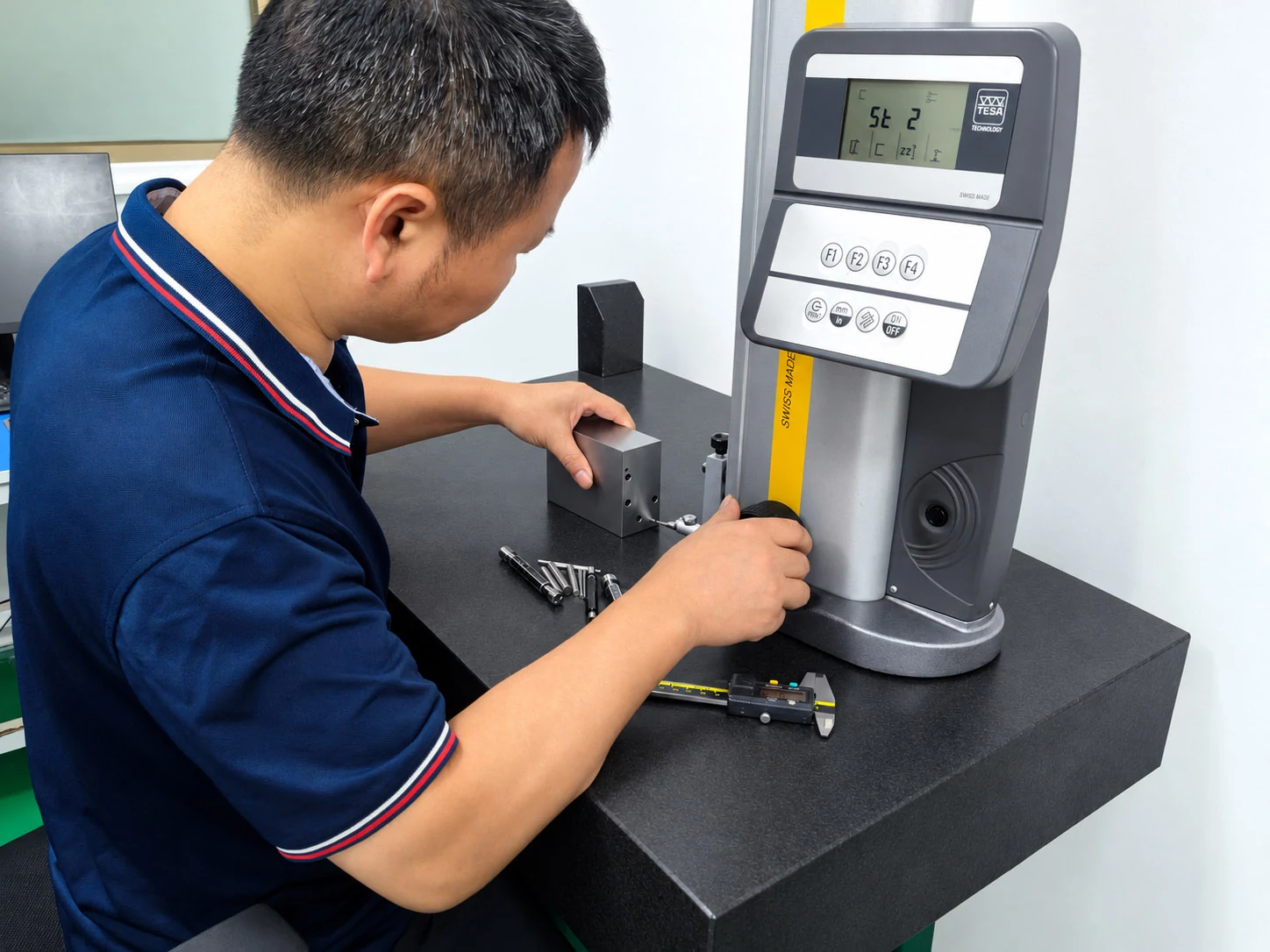
Feature-specific measurement
Bore measurement, thread gauges and roughness checks answer different questions. The method is chosen for the specified feature; one measurement does not establish the conformity of the complete cavity.
| Feature or requirement | Resource or method | What the evidence covers |
|---|---|---|
| Valve-cavity and port threads | Thread gauges appropriate to the specified thread and acceptance method. | The covered thread requirements; separate checks are needed for sealing bores, depths and surface condition. |
| Dimensions and feature relationships | CMM and other suitable dimensional instruments, selected for the required geometry and access. | Measured dimensions and relationships against the drawing. Restricted internal features need an agreed inspection approach. |
| Applicable sealing surfaces | Roughness measurement using a method suitable for the specified surface and access. | The measured surface requirement; a dimensional result or photograph does not establish roughness. |
| Material and required condition | Material documentation, with hardness or other additional checks where specified and agreed. | Evidence tied to the ordered grade and condition. A hardness reading alone does not identify the material grade. |
| Burr removal and delivery condition | Checks appropriate to the accessible edges, intersections and agreed cleaning and packaging scope. | The agreed component condition. Formal cleanliness testing, when required, has a separately defined method and scope. |
Material certificates and dimensional inspection reports can be provided. First-article and CMM reporting are agreed by project so the records cover the required features and drawing revision. Pressure and functional testing are not routine checks for our machined blocks; CMM measurement does not replace them or verify cleanliness.
Where formal component cleanliness evidence is required, the third-party test method, sample condition and acceptance limits are agreed separately. The internal cleaning operation shown on this page is not a cleanliness laboratory test.
Review inspection capability Review third-party cleanliness verification Review project documentationQuestions about the factory and its resources
Can a machine list confirm whether you can make our manifold?
It is useful background, but the drawing, material, workholding, passage geometry and inspection requirements determine the actual manufacturing plan. Send the critical features with your enquiry so the relevant resources can be reviewed.
Do the photographs show Zhongwei’s own operations?
Yes. The photographs on this page were supplied by Zhongwei and show its workshop, tooling, component handling and measurement activities. They illustrate resources and operations; acceptance of an order is supported by its agreed records.
What information can support our supplier review?
Identify the processes and records you need to evaluate. We can discuss relevant manufacturing information and the agreed inspection documents while protecting confidential project details. Any visit or remote review needs its scope and availability confirmed.
Are pressure and functional tests part of routine block inspection?
No. Normal acceptance focuses on correct material and conformity to the approved drawing, including dimensions, threads, specified bore geometry, sealing-surface roughness and burr removal. System validation is a separate engineering responsibility.
Show us the feature you need to verify
Send the manifold drawing and model, material and condition, critical cavity or passage requirements, quantity and requested inspection records. If you are evaluating the factory for a project, tell us which processes or documents you want to review.
DWG, DXF, PDF and JPG drawings and STEP, X_T, IGS and SLDPRT models are accepted by email or WhatsApp. Complete manifold drawings are preferred; a schematic can start the discussion. Contact us before sharing confidential files if an NDA is needed.
Prepare your project information