
The thread is only one part of the valve interface
A cartridge valve cavity brings together threaded engagement, bore steps, sealing diameters, locating features and passage openings. An error in one of these features can affect installation or sealing even when the thread accepts the valve. Manufacturing starts with the complete cavity reference and its relationship to the manifold.
Depths and locating features
The drawing defines where the valve seats and how the stepped features relate. We review the tool geometry and depth references together, rather than treating each bore as an unrelated dimension.
Sealing areas and passage entries
Surface condition matters where seals contact the cavity. Passage intersections can introduce edges and burrs, so the machining sequence also needs a route for deburring, cleaning and the agreed checks.
For each project, the exact valve model and current manufacturer cavity drawing establish the interface. Our manufacturing work then translates that definition into tooling, setups and inspection. Detailed compatibility review belongs to the engineering stage.
Valve cavity and port review Cavity references and specificationsSelect tooling against the cavity and the material
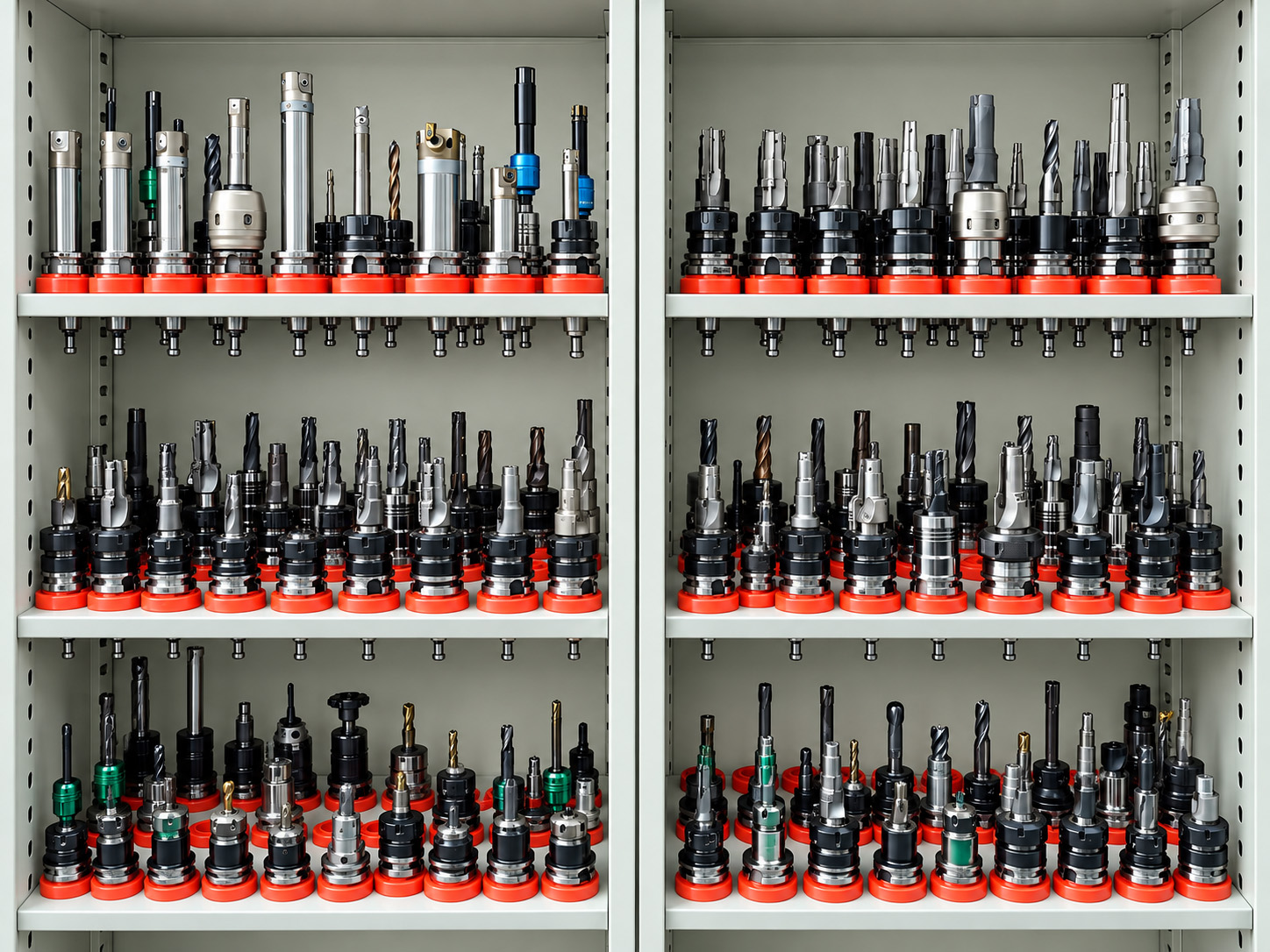
Zhongwei has accumulated dedicated screw-in cartridge valve cavity tooling through manifold projects, alongside experience developing tools for non-standard features. The workshop photograph above shows our tooling resources. For a new enquiry, we still check the particular cavity, drawing revision and material before confirming the tooling route.
An established cavity reference
Review the available tool geometry against the current drawing, then check its suitability for the workpiece material and access. Having a tool in storage does not remove the need to confirm its condition and the applicable dimensions.
A non-standard cavity
Use the valve supplier’s or customer’s controlled drawing to define the tooling requirement. Identify the sealing features, steps, depth relationships and inspection access before committing to tool preparation and sample timing.
The process can involve separate preparation and finishing operations. We consider the material left for finishing, the reach and clearance of the tool, and how later operations interact with the completed cavity. A dedicated tool supports the required geometry; the finished feature still needs verification.
Keep the cavity in the right relationship to the block
A correctly machined cavity can still be in the wrong position relative to a mounting face or intersecting passage. Fixture planning therefore connects the tool to the component’s datum scheme, not just to the visible face being machined.
Locate from the agreed datums
Choose locating references that connect to the drawing’s functional requirements. Review how the part is held and how critical relationships are maintained when the block moves between setups.
Plan access across faces
Valve cavities, ports and mounting features may be distributed across several faces. Check tool and fixture clearance, passage intersections and the remaining material around adjacent features as part of the operation plan.
For a cylinder-end component, the valve features also relate to the structural interface and any subsequent joining operations. The required delivery condition determines which features are inspected at each stage.
Multi-sided manifold machining Design for manufacturability reviewManage the finishing cut as the tool and material change
Steel sealing surfaces are a particular focus of our process work. In Q355B, GB 45 and applicable higher-strength steel projects, material condition, built-up edge and tool wear can affect the surface left by machining. A process that produces one acceptable sample must also account for what changes during a batch.
Match the cutting approach
Tool material and geometry, cutting speed and feed, finishing allowance and the final-cut strategy are considered together. For heat-treated steels, the specified condition and hardness belong in that review.
Connect tool life to feature checks
Tool-life planning and inspection checkpoints help manage changes in the resulting feature. A tool’s nominal size alone does not show the condition of its cutting edges or the quality of the surface it produces.
The acceptance requirement remains the specified surface on the actual component. Historical sealing-surface results from our cylinder-end work are explained on the product page with their material, feature and inspection-stage limits.
Steel cylinder-end sealing surfaces Material and delivery-condition considerationsVerify the feature, not just the presence of the tool
Inspection follows the requirement
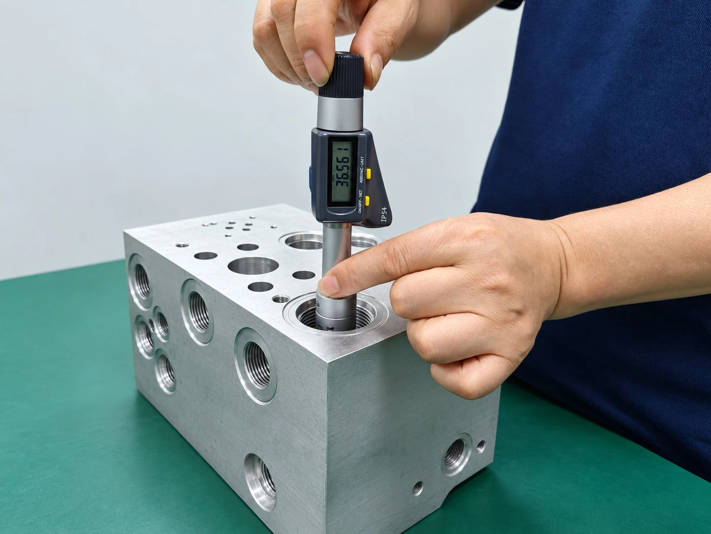
Our inspection resources support checks against approved drawings. The photograph shows dimensional measurement; surface roughness, thread acceptance and internal cleanliness require their own applicable methods and scope.
For internal features, measurement access needs consideration during process planning. Agree how critical dimensions, depths and surface requirements will be assessed before the first sample is made.
Dimensions and relationships
Cavity diameters, step depths, locating features and cross-face positions need suitable measurement methods. CMM measurement applies where the feature and probe access make it appropriate.
Threads and sealing surfaces
Thread checks and surface-roughness measurement answer different questions. A successful thread check does not establish that the adjacent sealing diameter, depth or surface finish meets the drawing.
Removing burrs and retained chips is a further part of the manufacturing route. Dimensional inspection does not demonstrate internal cleanliness, pressure integrity or valve function. Required inspection records and any separate tests are agreed for the project.
Inspection and metrology Deburring and cleaningCarry sample approval into the next production run
1. Establish the manufacturing basis
Connect the approved cavity revision, material condition, tool requirements, fixture references and critical checks before sample production.
2. Resolve the sample findings
Review measured results and customer assembly feedback. Record approved changes rather than allowing an informal adjustment to become an undocumented production requirement.
3. Maintain the repeat-order basis
Use the released revision, agreed setups and inspection points for repeat supply. Changes in the cavity drawing, material or finish require review of the affected tooling and process decisions.
For existing-part enquiries, existing samples and inspection results can help identify the features that need special attention. The controlled drawing set remains the basis for manufacture; a physical sample alone cannot define every tolerance or material requirement.
Prototype-to-batch production planningQuestions about tooling and cavity manufacture
Can you develop tooling for a non-standard valve cavity?
Yes. We review non-standard tooling requirements from a controlled valve-supplier or customer drawing. The cavity geometry, material condition, critical surfaces and inspection approach are assessed before confirming the tooling plan.
Do similar threads allow the same cavity tool to be used?
Not necessarily. Bore steps, depths, locating features and sealing diameters may differ. The proposed tool must be checked against the complete cavity drawing; thread similarity does not establish compatibility.
Does a dedicated cavity tool guarantee the surface finish?
No. Material condition, tool condition, finishing allowance and cutting parameters also influence the result. The applicable sealing surface must be checked against the specified requirement using an agreed method.
How long does new tooling take?
Timing depends on the drawing, tool requirements, availability and sample-validation scope. Share the required delivery date with the enquiry so tool preparation can be included in a project-specific schedule.
Can you help review a cavity that was rejected by another supplier?
Send the controlled cavity drawing, material condition, affected dimensions or surfaces and the inspection findings. We can review the manufacturing questions with you. Photographs or symptoms alone do not establish the cause of a rejection.
Bring us the cavity reference and the feature that matters
For a useful tooling review, send the valve model and current cavity drawing, the manifold drawing or model, material and condition, sample and repeat quantities, and the requested timing. Mark any difficult sealing feature or inspection access concern.
If there is an existing machining problem, include the measured result and where it was taken, alongside the drawing requirement. This helps connect the discussion to a specific feature and process decision.
Drawing formats and project submission guide