
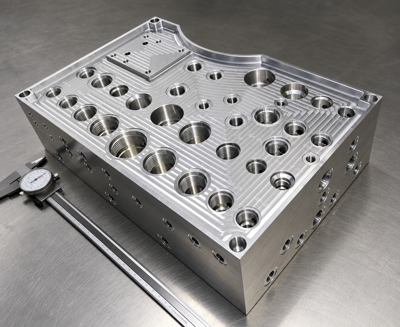
A valve model starts the review. The controlled references define the work.
An interface issue discovered during assembly can mean rework on a finished manifold. Reviewing it while the drawing is still being prepared allows the valve reference, machining route and acceptance requirements to be aligned before material is cut.
Valve identity and cavity drawing
Provide the manufacturer, complete valve model, specified cavity designation and drawing revision. Include relevant installation details. Similar model names or the same nominal thread do not establish the same sealing geometry or passage relationship.
Manifold drawing and model
Send the current 2D drawing and 3D model where available, including datums, cavity locations, cross-drilling and port labels. State which document governs if they differ; an unresolved difference needs clarification before the affected feature is machined.
Material, finish and acceptance
Include the material and condition, surface-treatment requirements and critical inspection features. A cavity that is correct before coating may still need allowances or masking to meet its final required dimensions.
If you have only a schematic and valve list, we can start by identifying the missing interface information. Before manufacture, the responsible design owner needs to approve the complete part definition. Review scope and any requested written deliverables are agreed for the project.
Keep cavities, mounting surfaces and external ports distinct
Screw-in cartridge valve cavities
The cavity includes more than its retaining thread: stepped bores, depths, sealing surfaces, transitions and connections to the internal passages. Use the valve supplier’s controlled reference or the exact applicable standardized cavity designation.
Subplate-mounted valve interfaces
Review the specified mounting pattern, port orientation, locating details, fixing threads and sealing face together. Where ISO 4401 applies, retain the exact mounting-surface designation and relevant valve drawing.
External connections and plugs
Specify the full connection and sealing arrangement. Metric O-ring ports, SAE ORB ports, BSPP/G and tapered-thread interfaces need their own applicable definitions. A thread callout alone can leave the required sealing features unresolved.
ISO 7789 covers cavities for two-, three- and four-port screw-in cartridge valves. ISO 4401 covers mounting surfaces for four-port directional control valves. Port specifications such as ISO 6149-1 address another interface family. These references cannot be substituted for one another simply because they appear on the same manifold.
Scope references: ISO 7789 cavity interfaces, ISO 4401 mounting surfaces and ISO 6149-1 metric O-ring ports. Use the standard edition and complete interface definition approved for the project.
Read the valve cavity reference guide Read the port and mounting interface guideLook beyond whether the valve can screw into the block
A thread-gauge result answers a thread question. It does not establish that every sealing bore, shoulder and passage intersection is correct. We review the features that define the complete interface, then connect each requirement to a manufacturing or inspection action.
| Review item | Question to resolve | Manufacturing handoff |
|---|---|---|
| Reference and revision | Are the valve list, cavity drawing, model and part drawing referring to the same approved interface? | Identify the governing reference and revision; resolve obsolete or conflicting information. |
| Thread and entry | Is the thread form, size, class where specified, usable length and entry geometry fully defined? | Retain the complete requirement and establish suitable thread-gauge checks; include the surrounding entry and sealing features. |
| Stepped bores and depths | Do diameters, shoulders and depths follow the cavity drawing and its datum basis? | Use those dimensions to plan tooling, finishing allowance and appropriate measurement access. |
| Sealing surfaces and transitions | Are the specified sealing diameters, surfaces, chamfers, radii and edge conditions preserved? | Keep the required geometry and roughness explicit; address burr removal without altering the intended interface. |
| Passage intersections and surrounding material | Do the specified drillings connect at the intended locations, with clearance from neighboring cavities and features? | Raise geometric conflicts or unclear wall requirements with the design owner. Plan the approved machining and deburring access. |
| Final condition and measurement | Will the chosen process and any surface treatment leave the feature in the condition required for acceptance? | Agree allowances or masking where relevant, the inspection stage and report coverage for critical features. |
The review identifies manufacturing questions; it does not approve the circuit function, establish a universal pressure rating or authorize a valve substitution. Material and structural decisions remain with the responsible design engineer.
How the review supports cartridge valve manifolds How mixed valve interfaces are handledResolve the ambiguity before it becomes a machined feature
The cavity code and model disagree
If the drawing calls for one cavity but the model shows a different step depth, flag the conflicting feature and references. Obtain the design owner’s instruction and the controlled update needed for manufacture. Do not silently select whichever version is easier to machine.
A replacement valve has a similar thread
Compare the proposed valve’s cavity reference and complete interface with the approved part definition. A matching thread is only one check. Any geometric change needs approval; circuit and valve-performance suitability require their own design assessment.
The port size is given, but the seal is not
If the callout leaves the sealing arrangement unclear, request the intended connection reference and mating fitting information. Confirm the required spotface, recess, entry or other specified features before choosing the machining and inspection route.
These are examples of clarification situations, not claims about a particular customer project. The useful outcome is an agreed requirement tied to the affected drawing revision, with unresolved items visible before production release.
Connect the interface review to tooling and shop-floor control
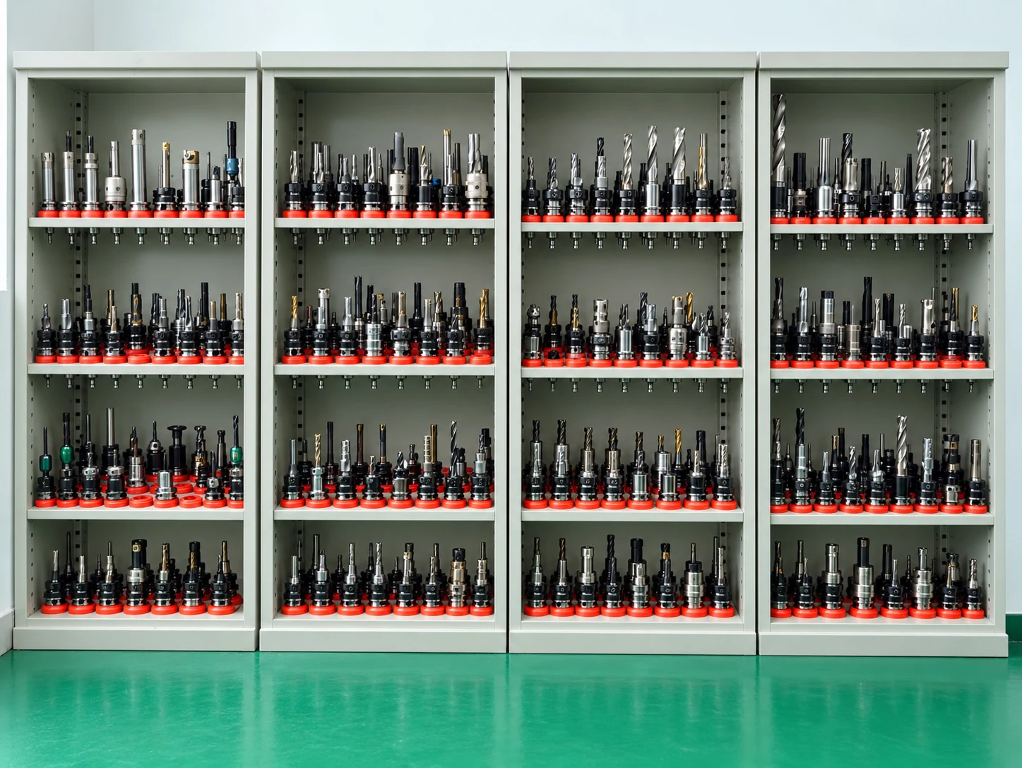
Check the tool against the actual geometry
Our dedicated cavity tooling and non-standard tool development support hydraulic interface manufacture. Review tool geometry and condition against the required steps and transitions. For a new or modified cavity, identify preparation needs before confirming the production plan.
Plan the feature in its material and location
Material condition, access, tool reach, finishing allowance and adjacent passages affect the process route. Plan cavity finishing with cross-drilling and deburring so later work preserves the required sealing surfaces and edge condition.
Tool availability alone does not confirm an interface is approved or a part is conforming. The drawing reference, process controls and inspection requirements must stay connected through manufacture.
Dedicated tooling and custom tool development Protecting cavity edges during deburring and cleaningCarry the agreed requirements into release and inspection
Record what has been resolved
Keep the relevant valve and interface references, drawing revisions and agreed changes with the manufacturing information. Confirm who approves any change and whether updated customer documents are needed.
Define the acceptance features
Identify the dimensions, datum relationships, thread-gauge requirements, bore geometry and sealing-surface roughness that need verification. Difficult-to-access features require an appropriate measurement approach agreed before production.
Agree the delivery evidence
Material certificates and dimensional reports can be supplied. Define the required report coverage, first-article or CMM scope and document references so the receiving team can connect results to the approved part.
Normal manifold acceptance verifies the specified material and conformity to the drawing, including burr removal. Pressure and functional testing are not routine checks for the machined block. Dimensional conformity also does not replace the valve supplier’s installation requirements or system-level validation.
Installation context: HydraForce cartridge installation guidance illustrates why assembly requirements are tied to the actual valve model. Refer to the supplier of the valve specified for your project; the reference is not a statement of brand authorization.
Drawing-based inspection and metrology Revision control and delivery recordsQuestions about cavity and interface review
Can you review a project from valve part numbers alone?
Part numbers can start the discussion. Add the manufacturer, cavity designation and current supplier drawing, together with the manifold drawing or available model. Identify missing information early; the approved interface definition is needed before manufacture.
Can valves from different manufacturers use the same cavity?
Some specified interfaces may be dimensionally compatible, but this must be established from the complete controlled references. Similar threads, appearance or size labels are insufficient. Dimensional compatibility does not by itself establish equivalent hydraulic function or approve a substitution.
Is a thread-gauge pass enough to accept a cartridge cavity?
No. It addresses the specified thread check. The cavity also has bore diameters, depths, transitions, sealing surfaces and passage relationships that need their own applicable verification.
Do you review subplate-mounted valves as well as cartridges?
Yes. Review includes the specified mounting face, port pattern and orientation, fixing and locating features, and sealing-surface requirements. Keep these references distinct from screw-in cartridge cavities and external connection ports.
What happens when the 2D drawing and 3D model differ?
Identify the conflict and ask the authorized design owner to confirm the governing requirement. Record the decision and obtain the necessary controlled update before machining the affected feature. A manufacturing convenience is not a basis for changing the design.
Can you work with a non-standard cavity?
We can review a customer or valve supplier drawing for tooling, machining and measurement needs. Any custom tool preparation, access limits and acceptance requirements must be resolved for the actual geometry. Availability and timing are confirmed for the project.
What should be agreed at the end of the review?
The references used, resolved questions, approved changes, remaining items preventing release, and the machining and inspection requirements needed for the part. Agree any formal review-document deliverable separately; the approved manufacturing definition remains the production basis.
Send the valve references with your manifold information
Provide the complete valve models and cavity drawings, current manifold drawing and model, material and condition, finish and critical inspection requirements. Highlight the question you need resolved: an unclear cavity, changed valve, sealing detail, connection specification or conflicting revision.
Complete manifold drawings are preferred. A schematic and valve list can start the review. Send DWG, DXF, PDF or JPG drawings and STEP, X_T, IGS or SLDPRT models by email or WhatsApp, with the sample and production quantities if available.
Prepare the project information